
Page 473 - Acquisition and Processing of Marine Seismic Data
P. 473
464 10. NORMAL MOVEOUT CORRECTION AND STACKING
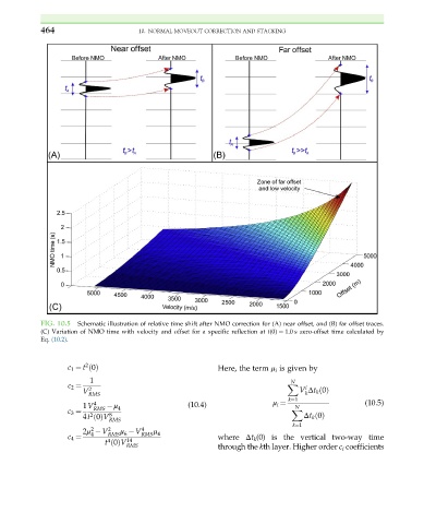
FIG. 10.5 Schematic illustration of relative time shift after NMO correction for (A) near offset, and (B) far offset traces.
(C) Variation of NMO time with velocity and offset for a specific reflection at t(0) ¼ 1.0 s zero-offset time calculated by
Eq. (10.2).
2
c 1 ¼ t 0ðÞ Here, the term μ i is given by
1 N
c 2 ¼ 2 X i
V RMS V Δt k 0ðÞ
k
k¼1
i
1V 4 RMS μ 4 (10.4) μ ¼ N (10.5)
c 3 ¼ 8 X
2
4t 0ðÞV Δt k 0ðÞ
RMS
k¼1
μ
2
2
4
2μ V RMS 6 RMS 4
μ V
4
c 4 ¼ 14 where Δt k (0) is the vertical two-way time
4
t 0ðÞV
RMS through the kth layer. Higher order c i coefficients