
Page 497 - Acquisition and Processing of Marine Seismic Data
P. 497
488 10. NORMAL MOVEOUT CORRECTION AND STACKING
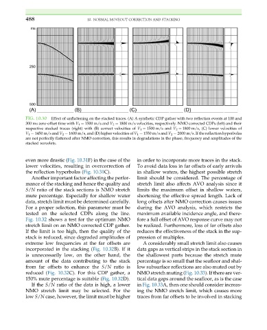
FIG. 10.30 Effect of unflattening on the stacked traces. (A) A synthetic CDP gather with two reflection events at 100 and
300 ms zero-offset time with V 1 ¼ 1500 m/s and V 2 ¼ 1800 m/s velocities, respectively. NMO corrected CDPs (left) and their
respective stacked traces (right) with (B) correct velocities of V 1 ¼ 1500 m/s and V 2 ¼ 1800 m/s, (C) lower velocities of
V 1 ¼ 1450 m/s and V 2 ¼ 1600 m/s, and (D) higher velocities of V 1 ¼ 1550 m/s and V 2 ¼ 2000 m/s. If the reflection hyperbolas
are not perfectly flattened after NMO correction, this results in degradations in the phase, frequency and amplitudes of the
stacked wavelets.
even more drastic (Fig. 10.31F) in the case of the in order to incorporate more traces in the stack.
lower velocities, resulting in overcorrection of To avoid data loss in far offsets of early arrivals
the reflection hyperbolas (Fig. 10.31C). in shallow waters, the highest possible stretch
Another important factor affecting the perfor- limit should be considered. The percentage of
mance of the stacking and hence the quality and stretch limit also affects AVO analysis since it
S/N ratio of the stack sections is NMO stretch limits the maximum offset in shallow waters,
mute percentage. Especially for shallow water shortening the effective spread length. Lack of
data, stretch limit must be determined carefully. long offsets after NMO correction causes issues
For a proper selection, this parameter must be during the AVO analysis, which restricts the
tested on the selected CDPs along the line. maximum available incidence angle, and there-
Fig. 10.32 shows a test for the optimum NMO fore a full offset of AVO response curve may not
stretch limit on an NMO corrected CDP gather. be realized. Furthermore, loss of far offsets also
If the limit is too high, then the quality of the reduces the effectiveness of the stack in the sup-
stack is reduced, since degraded amplitudes of pression of multiples.
extreme low frequencies at the far offsets are A considerably small stretch limit also causes
incorporated in the stacking (Fig. 10.32B). If it data gaps as vertical strips in the stack section in
is unnecessarily low, on the other hand, the the shallowest parts because the stretch mute
amount of the data contributing to the stack percentage is so small that the seafloor and shal-
from far offsets to enhance the S/N ratio is low subsurface reflections are also muted out by
reduced (Fig. 10.32C). For this CDP gather, a NMO stretch muting (Fig. 10.33). If there are ver-
150% mute percentage is suitable (Fig. 10.32D). tical data gaps around the seafloor, as is the case
If the S/N ratio of the data is high, a lower in Fig. 10.33A, then one should consider increas-
NMO stretch limit may be selected. For the ing the NMO stretch limit, which causes more
low S/N case, however, the limit must be higher traces from far offsets to be involved in stacking