
Page 495 - Acquisition and Processing of Marine Seismic Data
P. 495
486 10. NORMAL MOVEOUT CORRECTION AND STACKING
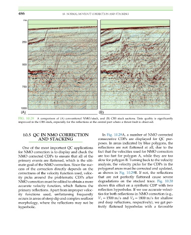
FIG. 10.28 A comparison of (A) conventional NMO/stack, and (B) CRS stack sections. Data quality is significantly
improved in the CRS stack, especially for the reflections at the central part where a thrust fault is observed.
10.5 QC IN NMO CORRECTION In Fig. 10.29A, a number of NMO corrected
AND STACKING consecutive CDPs are displayed for QC pur-
poses. In areas indicated by blue polygons, the
One of the most important QC applications reflections are not flattened at all, due to the
for NMO correction is to display and check the fact that the velocities used for NMO correction
NMO corrected CDPs to ensure that all of the are too fast for polygon A, while they are too
primary events are flattened, which is the ulti- slow for polygon B. Turning back to the velocity
mate goal of the NMO correction. Since the suc- analysis, the velocity picks for the CDPs in the
cess of the correction directly depends on the polygonal areas must be corrected and updated,
correctness of the velocity function used, veloc- as shown in Fig. 10.29B. If not, the reflections
ity picks around the problematic CDPs after that are not perfectly flattened cause severe
NMO correction must be edited to obtain a more degradations on the stacked trace. Fig. 10.30
accurate velocity function, which flattens the shows this effect on a synthetic CDP with two
primary reflections. Apart from improper veloc- reflection hyperbolas. If we use accurate veloci-
ity functions used, unflattening frequently ties for both reflections in NMO correction (e.g.,
occurs in areas of steep dip and complex seafloor V 1 ¼ 1500 m/s and V 2 ¼ 1800 m/s for shallow
morphology, where the reflections may not be and deep reflections, respectively), we get per-
hyperbolic. fectly flattened hyperbolas with a favorable