
Page 494 - Acquisition and Processing of Marine Seismic Data
P. 494
10.4 SPECIFIC STACKING METHODS 485
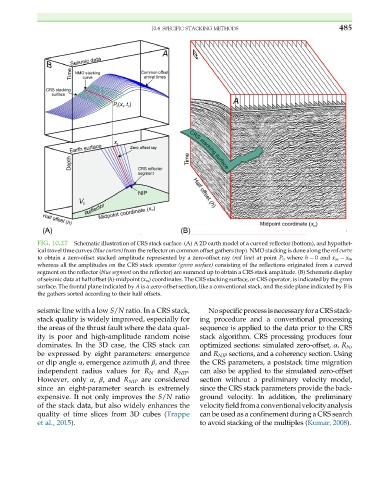
FIG. 10.27 Schematic illustration of CRS stack surface. (A) A 2D earth model of a curved reflector (bottom), and hypothet-
ical travel time curves (blue curves) from the reflector on common offset gathers (top). NMO stacking is done along the red curve
to obtain a zero-offset stacked amplitude represented by a zero-offset ray (red line) at point P 0 where h ¼ 0 and x m ¼ x 0 ,
whereas all the amplitudes on the CRS stack operator (green surface) consisting of the reflections originated from a curved
segment on the reflector (blue segment on the reflector) are summed up to obtain a CRS stack amplitude. (B) Schematic display
of seismic data at half offset (h)-midpoint (x m ) coordinates. The CRS stacking surface, or CRS operator, is indicated by the green
surface. The frontal plane indicated by A is a zero-offset section, like a conventional stack, and the side plane indicated by B is
the gathers sorted according to their half offsets.
seismic line with a low S/N ratio. In a CRS stack, NospecificprocessisnecessaryforaCRSstack-
stack quality is widely improved, especially for ing procedure and a conventional processing
the areas of the thrust fault where the data qual- sequence is applied to the data prior to the CRS
ity is poor and high-amplitude random noise stack algorithm. CRS processing produces four
dominates. In the 3D case, the CRS stack can optimized sections: simulated zero-offset, α, R N ,
be expressed by eight parameters: emergence and R NIP sections, and a coherency section. Using
or dip angle α, emergence azimuth β, and three the CRS parameters, a poststack time migration
independent radius values for R N and R NIP . can also be applied to the simulated zero-offset
However, only α, β, and R NIP are considered section without a preliminary velocity model,
since an eight-parameter search is extremely since the CRS stack parameters provide the back-
expensive. It not only improves the S/N ratio ground velocity. In addition, the preliminary
of the stack data, but also widely enhances the velocityfieldfromaconventionalvelocityanalysis
quality of time slices from 3D cubes (Trappe can be used as a confinement during a CRS search
et al., 2015). to avoid stacking of the multiples (Kumar, 2008).