
Page 528 - Acquisition and Processing of Marine Seismic Data
P. 528
11.6 POSTSTACK MIGRATION 519
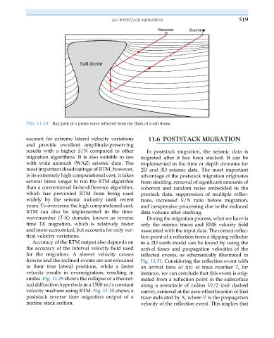
FIG. 11.28 Ray path of a prism wave reflected from the flank of a salt dome.
account for extreme lateral velocity variations 11.6 POSTSTACK MIGRATION
and provide excellent amplitude-preserving
results with a higher S/N compared to other In poststack migration, the seismic data is
migration algorithms. It is also suitable to use migrated after it has been stacked. It can be
with wide azimuth (WAZ) seismic data. The implemented in the time or depth domains for
most important disadvantage of RTM, however, 2D and 3D seismic data. The most important
is its extremely high computational cost; it takes advantage of the poststack migration originates
several times longer to run the RTM algorithm from stacking: removal of significant amounts of
than a conventional finite-difference algorithm, coherent and random noise embedded in the
which has prevented RTM from being used prestack data, suppression of multiple reflec-
widely by the seismic industry until recent tions, increased S/N ratio before migration,
years. To overcome the high computational cost, and inexpensive processing due to the reduced
RTM can also be implemented in the time- data volume after stacking.
wavenumber (T-K) domain, known as reverse During the migration process, what we have is
time TK migration, which is relatively faster only the seismic traces and RMS velocity field
and more economical, but accounts for only ver- associated with the input data. The correct reflec-
tical velocity variations. tion point of a reflection from a dipping reflector
Accuracy of the RTM output also depends on in a 2D earth model can be found by using the
the accuracy of the interval velocity field used arrival times and propagation velocities of the
for the migration. A slower velocity causes reflected events, as schematically illustrated in
frowns and the inclined events are not relocated Fig. 11.31. Considering the reflection event with
to their true lateral positions, while a faster an arrival time of t(x) at trace number 7, for
velocity results in overmigration, resulting in instance, we can conclude that this event is orig-
smiles. Fig. 11.29 shows the collapse of a theoret- inated from a reflection point in the subsurface
ical diffraction hyperbola in a 1500-m/s constant along a semicircle of radius Vt/2 (red dashed
velocity medium using RTM. Fig. 11.30 shows a curve), centered at the zero-offset location of that
poststack reverse time migration output of a trace indicated by X, where V is the propagation
marine stack section. velocity of the reflection event. This implies that