
Page 531 - Acquisition and Processing of Marine Seismic Data
P. 531
522 11. SEISMIC MIGRATION
NMO and stacking procedures are skipped and time arise in the semblance plots during the
a prestack migration can be preferred to obtain a velocity analysis (Fig. 11.32C). In the example
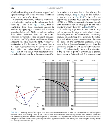
more correct subsurface image. semblance plot in Fig. 11.32C, the reflection
If there are intersecting reflectors with differ- hyperbolas indicated by A and B have velocities
ent inclination angles in the subsurface (indi- of 1500 and 2000 m/s, respectively, even though
cated by I and II in Fig. 11.32A), that is, both reflection signals propagate in the same
conflicting dips, these structures cannot be constant velocity layer (V 1 in Fig. 11.32A).
resolved by applying a conventional poststack If conflicting dips exist in the data, it may
migration followed by NMO correction-stacking not be possible to pick an individual velocity
flow. These reflectors form two individual for each particular reflection event. In velocity
reflection hyperbolas with different moveout analysis of conflicting dips, generally the veloc-
curvatures in CDP gathers, and hence different ity is picked at the point consistent with the over-
apparent velocities since the NMO velocity of all trend of the semblance contours, which
a reflection is dip dependent. The issue here is means that only one reflection hyperbola of the
that both hyperbolas have the same zero-offset same zero-offset time will be perfectly flattened.
time t(0), as schematically shown in Fig. 11.33 schematically shows this situation.
Fig. 11.32B. In this case, two enclosures at differ- If the velocity at point A (1500 m/s) is picked,
ent velocities but exactly at the same zero-offset the event A is flattened and B is overcorrected
FIG. 11.32 (A) Ray paths of the signal from source to receiver in the case of subsurface reflectors with conflicting dips
(reflector pieces indicated by I and II). (B) In such cases, two individual reflection hyperbolas with different curvatures
but the same t(0) time are obtained in CDP gathers. (C) Since the stacking velocities are dip dependent, two enclosures indi-
cating two different velocities corresponding to the same t(0) time occur in the semblance plots, preventing the picking of only
one velocity value for time t(0).