
Page 536 - Acquisition and Processing of Marine Seismic Data
P. 536
11.9 3D MIGRATION 527
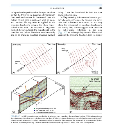
collapsed and repositioned at the apex locations today. It can be formulated in both the time
so that the hyperboloid becomes a hyperbola in and depth domains.
the crossline direction. In the second pass, the In 2D processing, it is assumed that the geol-
output of first-pass migration is used as input, ogy changes only along the seismic line direc-
and another 2D migration is applied in the tion and subsurface structures do not vary
crossline direction to collapse the whole hyper- along the orthogonal or crossline directions to
boloid to the apex. The one-pass 3D migration the survey line, which suggests that there are
method, however, treats the hyperboloid in the no out-of-plane reflections in the data
crossline and inline directions simultaneously (Fig. 11.37A), although they do exist. If the earth
and is an industry-standard imaging method varies in the crossline direction, then we simply
FIG. 11.37 (A) 2D processing assumes that the structures do not vary along the crossline direction. (B) Structures at cross-
line offsets sometimes have strong influences on the data. (C) Out-of-plane reflections are recorded and treated as ordinary 2D
reflections and cannot replace to their correct subsurface locations by 2D processing. (D) As a result, it is common for 2D lines
to include side-sweeps as steep linear or curved reflections remaining in the 2D image even after 2D migration.