
Page 538 - Acquisition and Processing of Marine Seismic Data
P. 538
11.10 DIP MOVEOUT 529
dimension (the side-sweeps) are completely The first part of Eq. (11.3) is the NMO term,
removed, resulting in a significantly improved while the second part is known as the DMO
illumination with sharp fault planes, and the term. According to Eq. (11.3), we can first apply
reflections have better trace-by-trace consistency. an NMO correction using the velocity of the
upperlying medium, and then a DMO correc-
tion is applied. Although NMO is valid in the
11.10 DIP MOVEOUT
CDP domain, the DMO term must be defined
in the common offset domain, which allows us
Poststack migrations generally do not yield
to discriminate the dipping events.
correct results since stack sections are not per-
Consecutive applications of NMO and DMO
fectly equivalent to zero-offset sections, due to
processes remove the offset and provide a more
the conflicting dip issues and in the case of lateral
accurate NMO correction for all available dips in
velocity variations, which leads to use of costly
the data. The poststack migration followed by
prestack algorithms. Prestack partial migration,
the NMO and DMO processing sequence will
or the DMO approach, provides a better stack
provide almost identical results with a prestack
section that is almost identical to the zero-offset
migration (Fig. 11.39) and with a considerably
section, so that one can apply a more economical
low cost, since the processing flow given in
poststack migration to the DMO output to obtain
Fig. 11.39 is much more computationally effec-
an image very similar to that from prestack
tive as compared to conventional prestack time
migration. The issue to be solved with the
migration. Furthermore, in contrast to NMO cor-
DMO process is conflicting dips, which originate
rection, which is rather sensitive to velocity
from the dip dependent stacking velocities. errors, constant velocity DMO is almost inde-
NMO correction becomes a dip filter in areas pendent from the velocities picked during the
of structurally dipping reflectors (Liner, 1999), velocity analysis (Liner, 1999).
and the processor picks the velocities in favor For the zero-offset case of identical source-
of only one dipping event (Fig. 11.33). receiver pairs on the earth’s surface, the reflector
Recalling the Levin equation, given by Eq. may be found at any depth and may have any
(10.7)
inclination in the subsurface. For instance, if
2
2
x cos ϕ the recorded zero-offset time is 1.0 s and the
2
2
t xðÞ ¼ t 0ðÞ + (11.2)
V 2 propagation velocity is 1000 m/s, we only have
where ϕ is the inclination of the reflector, V is the the information that the total distance traveled
velocity of the upperlying medium, and x is the will be 1000 m for all of the source-receiver pairs.
source-receiver offset. Considering the equality Based on this information, one can conclude that
2
2
sin ϕ +cos ϕ ¼ 1, we can divide Eq. (11.2) into there may be several possibilities to determine
two parts to get the correct location of the reflector, since it
may be located at any position on an ellipse
2
2
x 2 x sin ϕ
2
2
t xðÞ ¼ t 0ðÞ + (11.3) 1000 m away from all available source-receiver
V 2 V 2 pairs. The NMO term gives only the possibility
|fflfflfflfflfflffl{zfflfflfflfflfflffl} |fflfflfflffl{zfflfflfflffl}
NMO DMO of the horizontal reflector case just below the
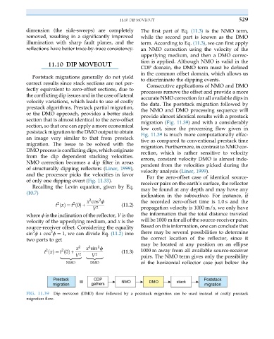
FIG. 11.39 Dip moveout (DMO) flow followed by a poststack migration can be used instead of costly prestack
migration flow.