
Page 533 - Acquisition and Processing of Marine Seismic Data
P. 533
524 11. SEISMIC MIGRATION
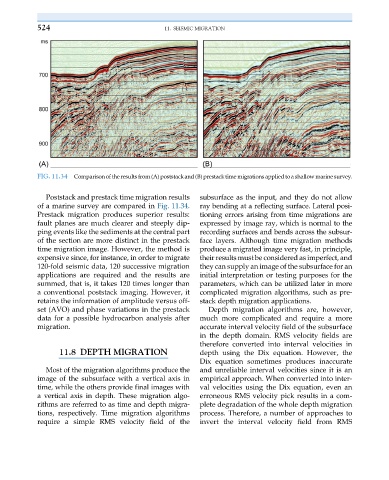
FIG. 11.34 Comparisonof the results from (A) poststackand (B) prestacktime migrations applied toa shallow marine survey.
Poststack and prestack time migration results subsurface as the input, and they do not allow
of a marine survey are compared in Fig. 11.34. ray bending at a reflecting surface. Lateral posi-
Prestack migration produces superior results: tioning errors arising from time migrations are
fault planes are much clearer and steeply dip- expressed by image ray, which is normal to the
ping events like the sediments at the central part recording surfaces and bends across the subsur-
of the section are more distinct in the prestack face layers. Although time migration methods
time migration image. However, the method is produce a migrated image very fast, in principle,
expensive since, for instance, in order to migrate their results must be considered as imperfect, and
120-fold seismic data, 120 successive migration they can supply an image of the subsurface for an
applications are required and the results are initial interpretation or testing purposes for the
summed, that is, it takes 120 times longer than parameters, which can be utilized later in more
a conventional poststack imaging. However, it complicated migration algorithms, such as pre-
retains the information of amplitude versus off- stack depth migration applications.
set (AVO) and phase variations in the prestack Depth migration algorithms are, however,
data for a possible hydrocarbon analysis after much more complicated and require a more
migration. accurate interval velocity field of the subsurface
in the depth domain. RMS velocity fields are
therefore converted into interval velocities in
11.8 DEPTH MIGRATION depth using the Dix equation. However, the
Dix equation sometimes produces inaccurate
Most of the migration algorithms produce the and unreliable interval velocities since it is an
image of the subsurface with a vertical axis in empirical approach. When converted into inter-
time, while the others provide final images with val velocities using the Dix equation, even an
a vertical axis in depth. These migration algo- erroneous RMS velocity pick results in a com-
rithms are referred to as time and depth migra- plete degradation of the whole depth migration
tions, respectively. Time migration algorithms process. Therefore, a number of approaches to
require a simple RMS velocity field of the invert the interval velocity field from RMS