
Page 535 - Acquisition and Processing of Marine Seismic Data
P. 535
526 11. SEISMIC MIGRATION
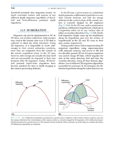
Kirchhoff poststack time migration results, its In the 2D case, a point source at a subsurface
depth converted version, and outputs of two depth generates a diffraction hyperbola in a con-
different depth migration algorithms of Kirch- stant velocity medium, and only the energy
hoff and finite-difference poststack depth reflected in the vertical plane of the seismic sec-
migrations. tion is correctly imaged by 2D migration
(Fig. 11.36A). In the 3D case, such a point source
produces a diffraction hyperboloid, which gives
11.9 3D MIGRATION a hyperbola when cut in any vertical slice of
inline or crossline directions (Fig. 11.36B). Kirch-
Migration can also be implemented in 3D. In hoff migration simply sums up the amplitudes
2D lines, out-of-plane reflections (side-sweeps) along the hyperbolas and over the surface of
may exist in the seismic data even if 2D data is hyperboloids in the 2D and 3D cases to their
collected in ideal dip strike directions. Using apex points, respectively.
2D migration, it is impossible to locate side- During earlier times, before implementing 3D
sweeps to their correct subsurface positions, migration algorithms using supercomputers
since they are originated from the outside of with adequate memory and power in the last
the seismic acquisition plane. In the 3D case, two decades, pseudo 3D (or two-pass) migration
however, side-sweeps are actually the data itself was used to image 3D data, which migrates the
and can successfully be migrated to their true data in the inline direction first and then the
locations after 3D migration. Today, 3D Kirch- crossline direction, using 2D time domain algo-
hoff prestack depth/time migrations have rithms. Use of different 2D migration algorithms
become standard for time or depth imaging in is possible for each pass. In the first pass, the dif-
the seismic processing industry. fraction hyperbolas along the inline direction are
FIG. 11.36 (A) A diffraction hyperbola is produced by a point source at depth in a 2D constant velocity medium, and only
the energy reflected in the vertical plane of the seismic section is correctly imaged by 2D migration. (B) A diffraction hyper-
boloid is produced by a point source in a 3D constant velocity medium. When vertically cut in the inline or crossline directions,
2D diffraction hyperbolas are obtained.