Page 100 - Adsorption, Ion Exchange & Catalysis- 2007, Elsevier - Copy
P. 100

Else_AIEC-INGLE_cH003.qxd  7/13/2006  1:45 PM  Page 96
                    96                               3. Heterogeneous Processes and Reactor  Analysis
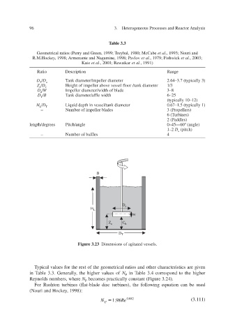

                                                     Table 3.3

                       Geometrical ratios (Perry and Green, 1999; T 1980; McCabe  ybal, re  et al  ., 1993; Nouri and
                     R.M.Hockey, 1998; Armenante and Nagamine, 1998; P a vlo v   et al  ., 1979; Fishwick   et al  ., 2003;
                                         Kato   et al  ., 2001; Re w atkar   et al  ., 1991)

                       Ratio   Description                      Range
                       D  T  / D  a  Tank diameter/impeller diameter  2.64–3.7 (typically 3)
                       Z / D  T    Height of impeller aboessel floor /tank diameter e v v  1/3
                        a
                       D  a  / W   Impeller diameter/width of blade  3–8
                       D  T  / B   Tank diameter/affle width  6–25
                                                                            (typically 10–12)
                       H  L  / D  T  Liquid depth in vessel/tank diameter  0.67–1.5 (typically 1)
                         –        Number of impeller blades  3 (Propellers)
                                                                            6 (Turbines)
                                                                            2 (P addles)
                    length/degrees  Pitch/angle           0–45—60° (angle)
                                                                            1–2   D  a  (pitch)
                         –        Number of baf fles          4


                                                B


                                                          D  a
                                             H  L
                                                              w
                                                    Z  a  C  b

                                                         D  T

                                        Figure 3.23  Dimensions of agitated v essels.


                      Typical values for the rest of the geometrical ratios and other characteristics are gi en v
                    in Table 3.3. Generally the higher values of   N  P  in Table 3.4 correspond to the higher
                     ,
                    Reynolds numbers, where   N  P  becomes practically constant (Figure 3.24).
                      For Rushton turbines (flat-blade disc turbines), the following equation can be used
                    y e (Nouri and Hock, 1998):

                                                 N    1.98    Re  0.082               (3.111)
                                                   P
   95   96   97   98   99   100   101   102   103   104   105