Page 103 - Adsorption, Ion Exchange & Catalysis- 2007, Elsevier - Copy
P. 103

Else_AIEC-INGLE_cH003.qxd  7/13/2006  1:45 PM  Page 99
                  3.3 T w Reactors o-Phase Agitated             99


                    For the rest of the parameters, SI units are used. For the evaluation of density difference,
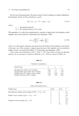
                  the hydraulic density for the solid phase is used:

                                                           )(      )                (3.115)
                                                      (1
                                              h   L      p  s  L
                  where:
                              the particle porosity
                           p
                              the skeletal density of the solid.
                           s
                  The parameter   S is called the proportionality constant or shape f and depends on the , actor
                  impeller and vessel geometry (Armenante and Nagamine, 1998):


                                                 D     s 2    C  
                                           S   s  1   T    exp  s  3   b        (3.116)
                                                 D        D  
                                                   a           T
                  where   C  b  is the impeller clearance measured from the bottom of the impeller to the bottom
                  of the tank, in m.  The constants   s depend upon the type of the impeller and for c ,  ylindrical
                                            i
                  baffled vessels, are presented in T1998). able 3.5 (Armenante and Nagamine,
                    These values were obtained for 1/48     C / D  T    1/2.5. The  of  alues  v  S  gi en by McCabe v
                                                    b
                  v directly for seeral types of impellers (McCabe   et al  ., 1993) are shoT able 3.6. wn in


                                                  Table 3.5
                                             Constants of parameter   S .
                         Impeller type                          s        s      s
                                                                 1       2      3
                         Flat blade disc turbine with six blades  0.99  1.4  2.18
                         Straight blade open turbine with six blades  1.43  1.2  1.95
                         Pitched-blade (45°) turbine with six blades  2.28  0.83  0.65
                         Fluidfoil Chemineer HE-3 impeller  3.49  0.79  0.66


                                                  Table 3.6
                                            Value of the shape factor   S .

                  Impeller type                                     D  / D    D  / Z  S
                                                                     T  a      T  a
                  Flat-blade disc turbine with six blades (  D  / W    5,  N    6.2)  2  4  4.1
                                                a       p
                                                                    3        4      7.5
                  Paddle with two blades (  D  / W    4,  N    2.5)  2    4      4.8
                                     a       p
                                                                    3        4      8
                                                                    4        4      12.5
                  Propeller with three blades (  N    0.5)       3        4      6.5
                                        p
                                                                    4        4      8.5
                                                                    4        2.5  9.5
   98   99   100   101   102   103   104   105   106   107   108