
Page 101 - Adsorption, Ion Exchange & Catalysis- 2007, Elsevier - Copy
P. 101
Else_AIEC-INGLE_cH003.qxd 7/13/2006 1:45 PM Page 97
3.3 T o-Phase Agitated w Reactors 97
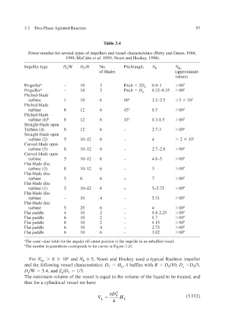
Table 3.4
Power number for seeral types of impellers and vessel characteristics (Perry and Green, 1984, v
1999; McCabe et al . 1993; Nouri and Hock 1998) , e y
Impeller type D a / W D T / B No. Pitch/angle N P N Re
of blades (approximate
values)
Propeller a – 10 3 Pitch 2D a 0.9–1 10 3
Propeller a – 10 3 Pitch D a 0.32–0.35 10 4
Pitched-blade
3
turbine 4 10 6 60° 2.2–2.5 10 2
Pitched-blade
turbine 8 12 6 45° 1.5 10 4
Pitched-blade
turbine (6) b 8 12 6 45° 1.3-1.5 10 3
Straight-blade open
Turbine (4) 8 12 6 – 2.7-3 10 4
Straight-blade open
turbine (2) 5 10–12 6 – 4 2 10 3
Curved-blade open
turbine (5) 8 10–12 6 – 2.7–2.8 10 4
Curved-blade open
turbine 5 10–12 6 – 4.8–5 10 4
Flat-blade disc
turbine (3) 8 10–12 6 – 3 10 4
Flat-blade disc
turbine 5 6 6 – 7 10 4
Flat-blade disc
turbine (1) 5 10–12 6 – 5–5.75 10 4
Flat-blade disc
turbine – 10 4 – 5.31 10 4
Flat-blade disc
turbine 5 25 6 – 4 10 4
Flat paddle 4 10 2 – 1.8-2.25 10 4
Flat paddle 6 10 2 – 1.7 10 4
Flat paddle 8 10 2 – 1.15 10 4
Flat paddle 6 10 4 – 2.75 10 4
Flat paddle 6 10 6 – 3.82 10 4
a The same value holds for the angular off-center position of the impeller in an unbaf essel. fled v
b The number in parenthesis corresponds to the curves in Figure 3.24.
For N 8 10 4 and N ≅ 5, Nouri and Hocky used a typical Rushton impeller
e
Re P
and the following vessel characteristics: D H , 4 baffles with B D /10, D D /3,
T L T a T
D /W 5.4, and Z / D 1/3.
a a T
The minimum volume of the vessel is equal to the volume of the liquid to be treated, and
thus for a cylindrical vessel we ha v e
D 2
V L T H T (3.112)
4