
Page 170 - Adsorption, Ion Exchange & Catalysis- 2007, Elsevier - Copy
P. 170
Else_AIEC-INGLE_cH003.qxd 7/13/2006 1:45 PM Page 166
166 3. Heterogeneous Processes and Reactor Analysis
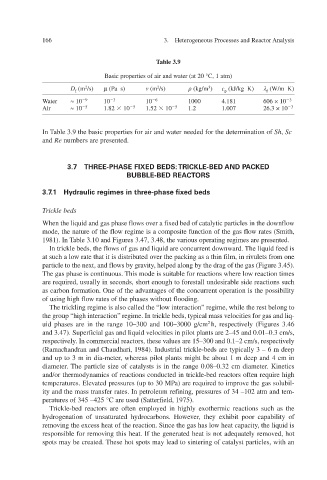
Table 3.9
Basic properties of air and water (at 20 °C, 1 atm)
D f (m 2 /s) µ (P s) a (m 2 /s) (kg/m 3 ) c p (kJ/kg K) (W/m K)
f
Water ≈ 10 9 10 3 10 6 1000 4.181 606 × 10 3
Air ≈ 10 5 1.82 10 5 1.52 10 5 1.2 1.007 26.3 × 10 3
In Table 3.9 the basic properties for air and water needed for the determination of Sh , Sc
and Re numbers are presented.
3.7 THREE-PHASE FIXED BEDS:TRICKLE-BED AND PACKED
BUBBLE-BED REACTORS
3.7.1 Hydraulic regimes in three-phase fixed beds
Trickle beds
When the liquid and gas phase flows over a fixed bed of catalytic particles in the downflow
mode, the nature of the flow regime is a composite function of the gas flow rates (Smith,
1981). In Table 3.10 and Figures 3.47, 3.48, the v gimes are presented. arious operating re
In trickle beds, the flows of gas and liquid are concurrent doThe liquid feed is wnw ard.
at such a low rate that it is distriber the packing as a thin f in rivulets from one v uted o ilm,
ws by gra, particle to the next, and flo vity helped along by the drag of the gas (Figure 3.45).
The gas phase is continuous. This mode is suitable for reactions where low reaction times
are required, usually in seconds, short enough to forestall undesirable side reactions such
as carbon formation. One of the advantages of the concurrent operation is the possibility
of using high flow rates of the phases without flooding.
The trickling regime is also called the “low interaction” re while the rest belong to gime,
the group “high interaction” retypical mass v gime. In trickle beds, elocities for gas and liq-
uid phases are in the range 10–300 and 100–3000 g/cm 2 h, respectiely (Figures 3.46 v
and 3.47). Superficial gas and liquid velocities in pilot plants are 2–45 and 0.01–0.3 cm/s,
respectively. In commercial reactors, these v respecti alues are 15–300 and 0.1–2 cm/s, ely v
(Ramachandran and Chaudhari, 1984). Industrial trickle-beds are typically 3 – 6 m deep
,
and up to 3 m in dia-meter whereas pilot plants might be about 1 m deep and 4 cm in
diameter. The particle size of catalysts is in the range 0.08–0.32 cm diameter. Kinetics
and/or thermodynamics of reactions conducted in trickle-bed reactors often require high
v temperatures. Eleated pressures (up to 30 MPa) are required to improe the gas solubil- v
ining,
ity and the mass transfer rates. In petroleum ref pressures of 34 –102 atm and tem-
peratures of 345 –425 °C are used (Satterf 1975). ield,
Trickle-bed reactors are often employed in highly exothermic reactions such as the
hydrogenation of unsaturated hydrocarbons. Ho they exhibit poor capability of
we
,
er
v
, w heat capacity removing the excess heat of the reaction. Since the gas has lo the liquid is
responsible for removing this heat. If the generated heat is not adequately remo hot ed, v
spots may be created. These hot spots may lead to sintering of catalyst particles, with an