
Page 129 - Advanced Design Examples of Seismic Retrofit of Structures
P. 129
Example of an RC Building Retrofitted by RC Shear Walls Chapter 3 121
the architectural drawings, as-built sketches, different details, and material pro-
perties should be available. The accuracy and completeness of the data depends
on the “target” of seismic retrofit strategy and the method of structural analysis.
The “performance objective” in the seismic retrofit strategy is decided during
the qualitative evaluation of the building in coordination with the owner of the
building. The decision depends on factors including the quality of the building
and its importance. Because it was planned to use the retrofitted building as
headquarter of four deputies of the municipality of Tehran, the importance of
the building is high and the target of the retrofit strategy is “enhanced.” As a
result, and in the absence of any information regarding the present conditions
of the building, data collection and field testing were performed in order to pro-
vide the conditions based on which the knowledge factors of 1.0 can be used for
the “enhanced” performance objective.
2
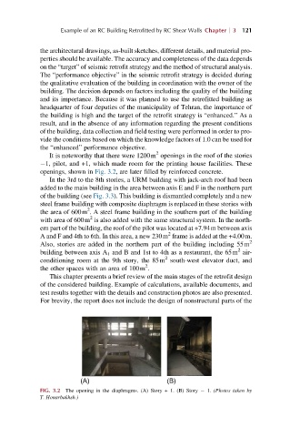
It is noteworthy that there were 1200m openings in the roof of the stories
1, pilot, and +1, which made room for the printing house facilities. These
openings, shown in Fig. 3.2, are later filled by reinforced concrete.
In the 3rd to the 8th stories, a URM building with jack-arch roof had been
added to the main building in the area between axis E and F in the northern part
of the building (see Fig. 3.3). This building is dismantled completely and a new
steel frame building with composite diaphragm is replaced in these stories with
2
the area of 600m . A steel frame building in the southern part of the building
2
with area of 600m is also added with the same structural system. In the north-
ern part of the building, the roof of the pilot was located at +7.94m between axis
2
A and F and 4th to 6th. In this area, a new 230m frame is added at the +4.00m.
Also, stories are added in the northern part of the building including 55m 2
2
building between axis A 1 and B and 1st to 4th as a restaurant, the 65m air-
2
conditioning room at the 9th story, the 85m south-west elevator duct, and
2
the other spaces with an area of 100m .
This chapter presents a brief review of the main stages of the retrofit design
of the considered building. Example of calculations, available documents, and
test results together with the details and construction photos are also presented.
For brevity, the report does not include the design of nonstructural parts of the
(A) (B)
FIG. 3.2 The opening in the diaphragms. (A) Story + 1. (B) Story 1. (Photos taken by
T. Honarbakhsh.)