
Page 135 - Advanced Design Examples of Seismic Retrofit of Structures
P. 135
Example of an RC Building Retrofitted by RC Shear Walls Chapter 3 127
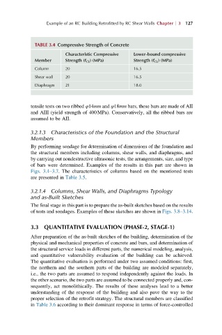
TABLE 3.4 Compressive Strength of Concrete
Characteristic Compressive Lower-bound compressive
Member Strength (f CE ) (MPa) Strength (f CL ) (MPa)
Column 20 16.5
Shear wall 20 16.5
Diaphragm 21 18.0
tensile tests on two ribbed φ14mm and φ18mm bars, these bars are made of AII
and AIII (yield strength of 400MPa). Conservatively, all the ribbed bars are
assumed to be AII.
3.2.1.3 Characteristics of the Foundation and the Structural
Members
By performing sondage for determination of dimensions of the foundation and
the structural members including columns, shear walls, and diaphragms, and
by carrying out nondestructive ultrasonic tests, the arrangements, size, and type
of bars were determined. Examples of the results in this part are shown in
Figs. 3.4–3.7. The characteristics of columns based on the mentioned tests
are presented in Table 3.5.
3.2.1.4 Columns, Shear Walls, and Diaphragms Typology
and as-Built Sketches
The final stage in this part is to prepare the as-built sketches based on the results
of tests and sondages. Examples of these sketches are shown in Figs. 3.8–3.14.
3.3 QUANTITATIVE EVALUATION (PHASE-2, STAGE-1)
After preparation of the as-built sketches of the building, determination of the
physical and mechanical properties of concrete and bars, and determination of
the structural service loads in different parts, the numerical modeling, analysis,
and quantitative vulnerability evaluation of the building can be achieved.
The quantitative evaluation is performed under two assumed conditions: first,
the northern and the southern parts of the building are modeled separately,
i.e., the two parts are assumed to respond independently against the loads. In
the other scenario, the two parts are assumed to be connected properly and, con-
sequently, act monolithically. The results of these analyses lead to a better
understanding of the response of the building and also pave the way to the
proper selection of the retrofit strategy. The structural members are classified
in Table 3.6 according to their dominant response in terms of force-controlled