
Page 212 - Advanced Design Examples of Seismic Retrofit of Structures
P. 212
Example of a Steel Frame Building With Masonry Infill Walls Chapter 4 205
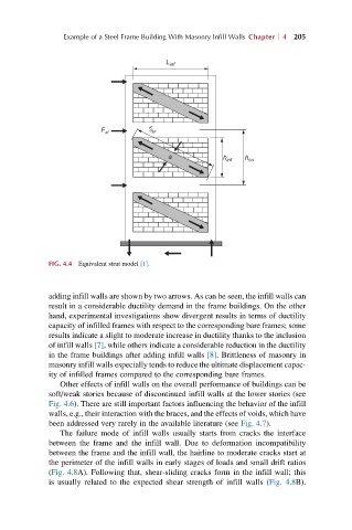
L inf
F xi r inf
a h inf h co
FIG. 4.4 Equivalent strut model [1].
adding infill walls are shown by two arrows. As can be seen, the infill walls can
result in a considerable ductility demand in the frame buildings. On the other
hand, experimental investigations show divergent results in terms of ductility
capacity of infilled frames with respect to the corresponding bare frames; some
results indicate a slight to moderate increase in ductility thanks to the inclusion
of infill walls [7], while others indicate a considerable reduction in the ductility
in the frame buildings after adding infill walls [8]. Brittleness of masonry in
masonry infill walls especially tends to reduce the ultimate displacement capac-
ity of infilled frames compared to the corresponding bare frames.
Other effects of infill walls on the overall performance of buildings can be
soft/weak stories because of discontinued infill walls at the lower stories (see
Fig. 4.6). There are still important factors influencing the behavior of the infill
walls, e.g., their interaction with the braces, and the effects of voids, which have
been addressed very rarely in the available literature (see Fig. 4.7).
The failure mode of infill walls usually starts from cracks the interface
between the frame and the infill wall. Due to deformation incompatibility
between the frame and the infill wall, the hairline to moderate cracks start at
the perimeter of the infill walls in early stages of loads and small drift ratios
(Fig. 4.8A). Following that, shear-sliding cracks form in the infill wall; this
is usually related to the expected shear strength of infill walls (Fig. 4.8B).