
Page 48 - Advanced Design Examples of Seismic Retrofit of Structures
P. 48
40 Advanced Design Examples of Seismic Retrofit of Structures
As per ASCE 41 [2], the structure contains a complete, well-defined load
path, including structural elements and connections, that serves to transfer
the inertial forces associated with the mass of all elements of the building to
the foundation. The load path is a path through which seismic forces are deliv-
ered from the point at which inertial forces are generated in the structure to the
foundation and, ultimately, the supporting soil.
2.5.2 Diaphragm
The diaphragms of the majority of masonry school buildings in Iran are either
filler-joist or jack-arch. The former is usually considered as a rigid diaphragm
and the latter is considered as flexible according to the Iranian code of practice
for seismic resistant design of buildings [7]. Based on [9], the assumed live
loads in the educational spaces, corridors, and roofs are assumed to be 350,
2
500, and 150kg/m , respectively.
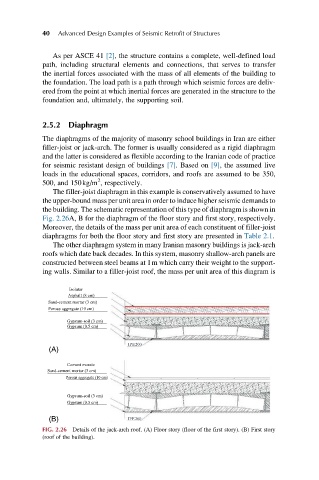
The filler-joist diaphragm in this example is conservatively assumed to have
the upper-bound mass per unit area in order to induce higher seismic demands to
the building. The schematic representation of this type of diaphragm is shown in
Fig. 2.26A, B for the diaphragm of the floor story and first story, respectively.
Moreover, the details of the mass per unit area of each constituent of filler-joist
diaphragms for both the floor story and first story are presented in Table 2.1.
The other diaphragm system in many Iranian masonry buildings is jack-arch
roofs which date back decades. In this system, masonry shallow-arch panels are
constructed between steel beams at 1m which carry their weight to the support-
ing walls. Similar to a filler-joist roof, the mass per unit area of this diagram is
Isolator
Asphalt (8 cm)
Sand-cement mortar (3 cm)
Porous aggregate (10 cm)
Gypsum-soil (3 cm)
Gypsum (0.5 cm)
IPE200
(A)
Cement mosaic
Sand-cement mortar (3 cm)
Porous aggregate (10 cm)
Gypsum-soil (3 cm)
Gypsum (0.5 cm)
(B) IPE200
FIG. 2.26 Details of the jack-arch roof. (A) Floor story (floor of the first story). (B) First story
(roof of the building).