
Page 49 - Advanced Design Examples of Seismic Retrofit of Structures
P. 49
Example of a Two-Story Unreinforced Masonry Building Chapter 2 41
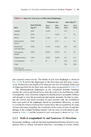
TABLE 2.1 Mass Per Unit Area of Filler-Joist Diaphragm
2
Thickness (m) Mass (kg/m )
Mass Density Floor First Floor First
3
Item (kg/m ) Story Story Story Story
Asphalt 2200 0.050 – 110 –
Mosaic 2250 – 0.025 – 56
Bricks 1500 0.140 – 210 –
Sand-cement 2100 – 0.04 – 84
mortar
Reinforced 2500 0.100 0.100 250 250
concrete layer
Soil-gypsum 1600 0.010 0.010 16 16
mortar
Gypsum mortar 1300 0.005 0.005 6.5 6.5
Cement block 17 a 8 b 8 b 136 136
Total 730 550
a The unit is kg.
b
The number per unit area.
also assumed conservatively. The details of jack-arch diaphragm is shown in
Fig. 2.27A, B and for the diaphragms of the floor story and first story, respec-
tively. Furthermore, the details of the mass per unit area of each part of this type
of diaphragm both for the floor story and first story are presented in Table 2.2.
The aforementioned diaphragms in the considered masonry buildings
transfer the vertical and lateral forces from the roofs to the load-bearing walls.
Consequently, these structural components should possess acceptable stiffness
and strength to resist the gravitational and seismic demands. In order to calcu-
late the vertical and lateral demands on each masonry wall, the contribution
from each panel of the diaphragm should be determined. Moreover, in order
to consider the effects of torsion from lateral forces due to eccentricity of center
of mass and center of rigidity, the coordinates of the center of mass of each dia-
phragm in the example building together with the mass of each panel are pre-
sented in Table 2.3 and the location of each roof panel is shown in Fig. 2.28.
2.5.3 Walls in Longitudinal (X) and Transverse (Y) Directions
In masonry buildings, walls are the most important load-bearing structural com-
ponents both in vertical and lateral directions. According to several seismic