
Page 191 - Advanced Gas Turbine Cycles
P. 191
Chapter 8. Novel gas turbine cycles 151
Of course, there is no methane at exit from the PO reactor, and no oxygen. The
hydrogen content is quite high, over 15% and comparable to that in Lloyd’s example of the
steam/TCR cycle, but the CO content is also nearly 8%. It is interesting to note that
the calculated equilibrium concentrations of these combustible products from the reactor
are reduced through the PO turbine (because of the fall in temperature) before they are
supplied to the gas turbine combustor where they are fully combusted, but it is more likely
that the concentrations would be frozen near the entry values.
Newby et al. found that increasing the PO turbine pressure resulted in higher steam flow
(for a given pinch point temperature difference in the HRSG), increased PO turbine power
and overall plant efficiency. However, at the highest pressure of 100 bar attempts to
increase the steam flow further resulted in incomplete combustion in the main combustor
and the overall thermal efficiency did not increase substantially at this pressure level.
PO plant with Cot removal (02). Lozza and Chiesa [I31 have proposed a partial
oxidation CCGT plant with carbon dioxide removal, Cycle D2 of Table 8. lD, and this is
shown in Fig. 8.19. Now the syngas from a first PO reactor is cooled and fed to an
additional shift reactor and then to a chemical or physical absorption plant. C02 can thus
be removed and hydrogen rich syngas fed to the main combustion chamber of the gas
turbine plant, the exhaust gases from which pass through an HRSG, producing steam for a
bottoming steam cycle and the Po reactor. Lozza and Chiesa calculated a hydrogen molal
fraction of nearly 50% after the shift reaction and CO2 removal. The plant efficiency drops
to 48.5% from the figure of 56.1 % for a basic CCGT plant. The cost of electricity produced
was estimated to be comparable to that of the semi-closed plant of Cycle A2, i.e. an
increase of about 40% on that of the electricity produced by the basic CCGT plant.
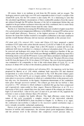
Complex cycle with partial oxidation and reforming (03). An ingenious cycle has been
proposed by Harvey et al. [I41 which combines both successive PO and chemical
recuperation in a semi-closed cycle, as illustrated in Fig. 8.20. Recycled exhaust gases
containing C02, H20 and N2 act as oxygen camers. Partial combustion (or oxidation)
takes place in successive combustors to which air is admitted (three in the proposed cycle,
but only two, for illustration, in the figure). Expansion downstream of the combustors
takes place through successive turbines. The exhaust gas from the last turbine is then
recycled to a ‘FG’ reformer to which methane is admitted (the gas has been compressed
and evaporatively water-cooled in three stages). However Rabovitser et al. 171, in a
discussion of this cycle, argued that since the water content of the exhaust gas streams is
high (5.25 mol of H20, 1 mol of C02 and 7.52 mol of N2 per mole of Cb supplied) the
reformer is more a steam reformer than a FG reformer.
The cycle is complex but highly efficient. This high efficiency comes from the
nature of the cycle (essentially a complex version of the intercooled, reheated,
recuperative CICICIBTBTBTX plant described in Chapter 3). As Harvey et al. argue,
the combustion irreversibility is reduced in the successive partial combustion steps, a
move towards reversible isothermal combustion.
Harvey et al. gave a parametric calculation of the thermal efficiency of this plant, as a
function of turbine inlet temperature, the reformer pinch point temperature difference
and the pressure level in the reformer (the compressor overall pressure ratio, r).