
Page 190 - Advanced Gas Turbine Cycles
P. 190
156 Advanced gas turbine cycles
C I
FUEL -
METHANE
EVAP EVAP CH4
IC AC
'
'
t TCR
1
HEAT
EXHAUST EXCHANGER
TO STACK 1
[COz,Nz,0zJWl WATER
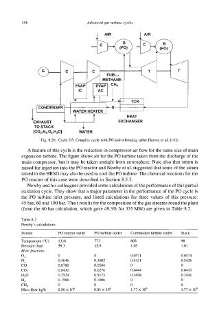
Fig. 8.20. Cycle D3. Complex cycle with PO and reforming (after Harvey et al. [14]).
A feature of this cycle is the reduction in compressor air flow for the same size of main
expansion turbine. The figure shows air for the PO turbine taken from the discharge of the
main compressor, but it may be taken straight from atmosphere. Note also that steam is
raised for injection into the PO reactor and Newby et al. suggested that some of the steam
raised in the HRSG may also be used to cool the PO turbine. The chemical reactions for the
PO reactor of this case were described in Section 8.5.3.
Newby and his colleagues provided some calculations of the performance of this partial
oxidation cycle. They show that a major parameter in the performance of the PO cycle is
the Po turbine inlet pressure, and listed calculations for three values of this pressure:
45 bar, 60 and 100 bar. Their results for the composition of the gas streams round the plant
(from the 60 bar calculation, which gave 49.3% for 335 MW) are given in Table 8.2.
Table 8.2
Newby's calculations
Stream PO reactor outlet PO turbine outlet Combustion turbine outlet Stack
Temperature ("C) 1316 773 608 98
Pressure (bar) 59.3 15.9 1.05 1.01
Mole fractions
02 0 0 0.057 1 0.0574
Nz 0.4646 0.3002 0.5421 0.5426
co 0.0780 0.0504 0 0
coz 0.0430 0.0276 0.0444 0.0443
H20 0.2529 0.5173 0.3498 0.349 I
HZ 0.1588 0.1006 0 0
CH4 0 0 0 0
Mass flow kgh 0.56 X 10' 0.81 X 10' 1.77 X IO6 1.77 X 10'