
Page 202 - Advanced Gas Turbine Cycles
P. 202
Chapter 9
THE GAS TURBINE AS A COGENERATION (COMBINED HEAT
AND POWER) PLANT
9.1. Introduction
The thermodynamics of thermal power plants has long been a classical area of study for
engineers. A conventional power plant receiving fuel energy (F), producing work (W) and
rejecting ‘non-useful’ heat (eA) to a sink at low temperature was illustrated earlier in
Fig. I. 1. The designer attempts to minimise the fuel input for a given work output because
this will clearly give economic benefit in the operation of the plant, minimising fuel costs
against the sales of electricity to meet the power demand.
The objectives of the designer of a combined heat and power plant are wider, for both
heat and work production. Fig. 9.1 shows a CHP or cogeneration (CG) plant receiving fuel
energy (FCG) and producing work (WcG). But useful heat as well as non-useful
heat (eNu),-- is now produced. Both the work and the useful heat can be sold, so the CHP
designer is not solely interested in high thermal efficiency, although the work output
commands a higher sale price than the useful heat output. Clearly, both thermodynamics
and economics will be of importance and these are developed in Ref. [I]. A much briefer
discussion of CHP is given here.
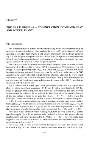
Fig. 9.2 shows how a simple open circuit gas turbine can be used as a cogeneration
plant: (a) with a waste heat recuperator (WHR) and (b) with a waste heat boiler (WHB).
Since the products from combustion have excess air, supplementary fuel may be burnt
downstream of the turbine in the second case. In these illustrations, the overall efficiency
of the gas turbine is taken to be quite low ((q&- = WcG/FcG = 0.25), where the
subscript CG indicates that the gas turbine is used as a recuperative cogeneration plant.
In Fig. 9.2a, the work output from the unfired plant is shown to be equal to unity and the
heat supply FCG = 4.0. Further, it is assumed that the useful heat supplied is = 2.25
and the unused non-useful heat is (QNu)cc = 0.75. An important parameter of this CHP
plant is the ratio of useful heat supplied to the work output, ,bG = (Qu)cc/Wcc = 2.25.
For a plant with a fired heat boiler, as in Fig. 9.2b, both the work output WCG and the
main heat supply FCG = F, are assumed to be unaltered at 1.0 and 4.0, respectively, but
supplementary fuel energy is supplied to the WHB, F2 = ISF, = 6.0. The useful heat
supplied is then assumed to increase to 7.2 and the non-useful heat rejected to be 1.8. Thus
the parameter h changes to 7.2.
For a site with a fixed power demand throughout the year, the unfired plant
illustrated in Fig. 9.2a is suitable for summer operation when the heat load is light.
I67