
Page 43 - Advanced Gas Turbine Cycles
P. 43
20 Advanced gas turbine cycles
2.3.1. Application of the exergyjux equation to a closed cycle
We next consider the application of the exergy flux equation to a closed cycle plant
based on the Joule-Brayton (JB) cycle (see Fig. 1.4), but with irreversible compression
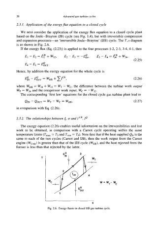
and expansion processes-an ‘irreversible Joule-Brayton’ (IJB) cycle. The T, s diagram
is as shown in Fig. 2.6.
If the exergy flux (Es. (2.23)) is applied to the four processes 1-2,2-3, 3-4,4-1, then
E~ - E~ = gm.
Hence, by addition the exergy equation for the whole cycle is
(2.26)
where W, = W, + WI2 = WT - W,-, the difference between the turbine work output
W, = W, and the compressor work input, Wc = - W12.
The corresponding ‘first law’ equations for the closed cycle gas turbine plant lead to
Qm - Qow= WT- WC= W,, (2.27)
in comparison with m. (2.26).
2.3.2. The relationships between a and I cR, ZQ
The exergy equation (2.26) enables useful information on the irreversibilities and lost
work to be obtained, in comparison with a Garnot cycle operating within the same
temperature limits (Tmm = T3 and Tmin = To). Note first that if the heat supplied QB is the
same to each of the two cycles (Carnot and LTB), then the work output from the Carnot
engine (WCAR) is greater than that of the LTB cycle (WuB), and the heat rejected from the
former is less than that rejected by the latter.
T
w - wT-
wC
8
Fig. 2.6. Exergy fluxes in clod UB gas turbine cycle.