Page 125 - Advanced engineering mathematics
P. 125

3.5 Impulses and the Delta Function  105


                                           Transients can be generated in a circuit during switching and can be harmful because they
                                        contain a broad spectrum of frequencies. If one of these is near the natural frequency of the
                                        system, introducing the transient can cause resonance to occur, resulting in oscillations large
                                        enough to cause damage. For this reason, engineers sometimes use a delta function to model a
                                        transient and study its effect on a circuit being designed.


                                 EXAMPLE 3.18
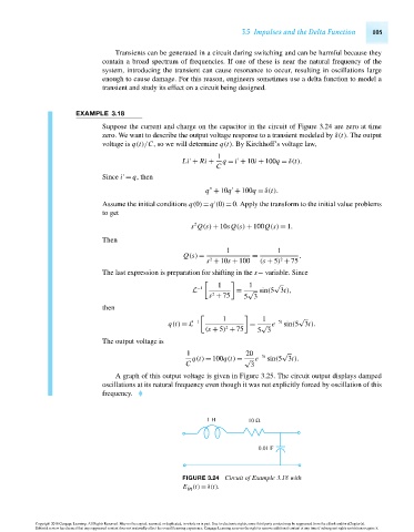
                                        Suppose the current and charge on the capacitor in the circuit of Figure 3.24 are zero at time
                                        zero. We want to describe the output voltage response to a transient modeled by δ(t). The output
                                        voltage is q(t)/C, so we will determine q(t). By Kirchhoff’s voltage law,
                                                                       1

                                                              Li + Ri +  q = i + 10i + 100q = δ(t).
                                                                       C

                                        Since i = q, then


                                                                    q + 10q + 100q = δ(t).
                                        Assume the initial conditions q(0) = q (0) = 0. Apply the transform to the initial value problems

                                        to get
                                                                 2
                                                                s Q(s) + 10sQ(s) + 100Q(s) = 1.
                                        Then
                                                                          1             1
                                                              Q(s) =             =            .
                                                                                         2
                                                                    s + 10s + 100  (s + 5) + 75
                                                                     2
                                        The last expression is preparation for shifting in the s− variable. Since
                                                                                       √
                                                                       1        1
                                                                  −1
                                                                L            = √ sin(5 3t),
                                                                     s + 75    5 3
                                                                      2
                                        then
                                                                                              √
                                                                         1          1
                                                                 −1                    −5t
                                                          q(t) = L              = √ e     sin(5 3t).
                                                                          2
                                                                    (s + 5) + 75  5 3
                                        The output voltage is
                                                               1               20        √
                                                                q(t) = 100q(t) = √ e −5t  sin(5 3t).
                                                               C                3
                                           A graph of this output voltage is given in Figure 3.25. The circuit output displays damped
                                        oscillations at its natural frequency even though it was not explicitly forced by oscillation of this
                                        frequency.


                                                                     1 H        10 Ω


                                                                                   0.01 F


                                                              FIGURE 3.24 Circuit of Example 3.18 with
                                                              E (t) = δ(t).
                                                               in


                      Copyright 2010 Cengage Learning. All Rights Reserved. May not be copied, scanned, or duplicated, in whole or in part. Due to electronic rights, some third party content may be suppressed from the eBook and/or eChapter(s).
                      Editorial review has deemed that any suppressed content does not materially affect the overall learning experience. Cengage Learning reserves the right to remove additional content at any time if subsequent rights restrictions require it.

                                   October 14, 2010  14:14  THM/NEIL    Page-105        27410_03_ch03_p77-120
   120   121   122   123   124   125   126   127   128   129   130