
Page 233 - Advanced thermodynamics for engineers
P. 233
220 CHAPTER 10 THERMODYNAMICS OF COMBUSTION
Enthalpy, H
(a) (b) Reactants
Insulation Products
R
H = H P C D
Gas turbine T
T R P
combustion B
chamber
- (Q ) s
p
- H
A
T R T P
T s Temperature, T
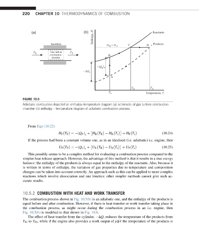
FIGURE 10.5
Adiabatic combustion depicted on enthalpy–temperature diagram (a) schematic of gas turbine combustion
chamber (b) enthalpy – temperature diagram of adiabatic combustion process.
From Eqn (10.22)
H P T P ¼ ðQ P Þ þ H R T R H R T s þ H P T s (10.24)
s
If the process had been a constant volume one, as in an idealised (i.e. adiabatic) i.c. engine, then
U P T P ¼ ðQ v Þ þ U R T R U R T s þ U P T s (10.25)
s
This possibly seems to be a complex method for evaluating a combustion process compared to the
simpler heat release approach. However, the advantage of this method is that it results in a true energy
balance: the enthalpy of the products is always equal to the enthalpy of the reactants. Also, because it
is written in terms of enthalpy, the variation of gas properties due to temperature and composition
changes can be taken into account correctly. An approach such as this can be applied to more complex
reactions which involve dissociation and rate kinetics: other simpler methods cannot give such ac-
curate results.
10.5.2 COMBUSTION WITH HEAT AND WORK TRANSFER
The combustion process shown in Fig. 10.5(b) is an adiabatic one, and the enthalpy of the products is
equal before and after combustion. However, if there is heat transfer or work transfer taking place in
the combustion process, as might occur during the combustion process in an i.c. engine, then
Fig. 10.5(b) is modified to that shown in Fig. 10.6.
The effect of heat transfer from the cylinder, DQ, reduces the temperature of the products from
T P1 to T P2 , while if the engine also provides a work output of pDV the temperature of the products is