Page 437 - Advanced thermodynamics for engineers
P. 437

18.1 LIQUEFACTION BY COOLING – METHOD (I)          427


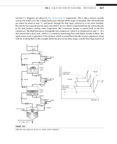
               relevant T–s diagrams are shown in Fig. 18.5(a) and (b) respectively. This is like a ternary cascade
               system, but in this case, the working fluid passes through all the stages of the plant. The carbon dioxide
               gas enters the plant at state ‘a’, and passes through the final stage, referred to as the snow chamber,
               because by this stage the gas has been converted to dry ice. Heat is transferred from the carbon dioxide
               to the final product causing some evaporation: this evaporated product is passed back to the first
               compressor. The fluid then passes through the first compressor, where it is compressed to state ‘c’. It is
               then passed into a flash tank, where it is cooled by transferring heat with liquid already in there: this
               again causes some evaporation of the product, which is passed back into the second compressor, along
               with the working fluid. In the example shown the process has three stages, and the final stage must be at


                          Cooling water
                                Q
                                   vapour
                                       g
                   h                           Work
                       liquid
                                           f
                         i           vapour
                                      Flash
                                      tank               Temperature, T           g   Vapour
                                                           temperature
                                   vapour                  Critical point            e    p tp
                                       e
                    j                                                  h               c
                       liquid                  Work            Liquid                      a  p = 1atm
                                                                     j   i        f         t = 25  C
                                                                                               o
                                           d
                         k            vapour              Triple point  l  k         d
                                                          temperature
                                     Flash                Solid
                                      tank                  n          m                b
                                     vapour
                   l
                      liquid           c
                                               Work                                  Entropy, S
                                  vapour   b
                             m
               1 kg CO  gas                 vapour
                     2
                        a


                 solid carbon dioxide  n
                      at 1 atm, -43  C
               FIGURE 18.5
               Plant for manufacture of dry ice (solid carbon dioxide).
   432   433   434   435   436   437   438   439   440   441   442