
Page 458 - Advanced thermodynamics for engineers
P. 458
19.1 HEAT TRANSFER NETWORK WITHOUT A PINCH PROBLEM 449
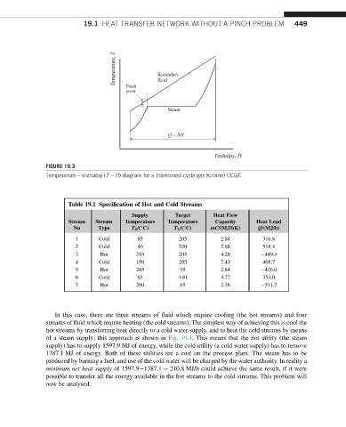
FIGURE 19.3
Temperature – enthalpy (T–H) diagram for a (combined cycle gas turbine) CCGT.
Table 19.1 Specification of Hot and Cold Streams
Supply Target Heat Flow
Stream Stream Temperature Temperature Capacity Heat Load
No Type T S /( C) T T /( C) mC/(MJ/hK) Q/(MJ/h)
1 Cold 95 205 2.88 316.8
2 Cold 40 220 2.88 518.4
3 Hot 310 205 4.28 449.4
4 Cold 150 205 7.43 408.7
5 Hot 245 95 2.84 426.0
6 Cold 65 140 4.72 354.0
7 Hot 280 65 2.38 511.7
In this case, there are three streams of fluid which require cooling (the hot streams) and four
streams of fluid which require heating (the cold streams). The simplest way of achieving this is cool the
hot streams by transferring heat directly to a cold water supply, and to heat the cold streams by means
of a steam supply; this approach is shown in Fig. 19.4. This means that the hot utility (the steam
supply) has to supply 1597.9 MJ of energy, while the cold utility (a cold water supply) has to remove
1387.1 MJ of energy. Both of these utilities are a cost on the process plant. The steam has to be
produced by burning a fuel, and use of the cold water will be charged by the water authority. In reality a
minimum net heat supply of 1597.9 1387.1 ¼ 210.8 MJ/h could achieve the same result, if it were
possible to transfer all the energy available in the hot streams to the cold streams. This problem will
now be analysed.