
Page 462 - Advanced thermodynamics for engineers
P. 462
19.3 STEP 2: INTERVAL HEAT BALANCES 453
Hot reservoir
(utilities)
Hot streams
Q
H = Q - Q
Cold streams Q
Cold reservoir
(utilities)
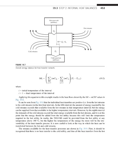
FIGURE 19.7
Overall energy balance for heat transfer network.
0 1
B X X C
C
@
dH i ¼ B ðmCÞ ðmCÞ cA ðT i T iþ1 Þ (19.2)
h
Hot Cold
i;iþ1 i;iþ1
where
i ¼ initial temperature of the interval
i þ 1 ¼ final temperature of the interval
Applying this equation to this example results in the heat flows shown by the dH ¼ mCdT values in
Fig. 19.8.
It can be seen from Fig. 19.8 that the individual heat transfers are positive (i.e. from the hot streams
to the cold streams) in the first four intervals. In the fifth interval, the amount of energy required by the
cold streams exceeds that available from the hot streams in that temperature interval, but the energy
can be supplied from that available in the higher temperature intervals. However, by the eighth interval
the demands of the cold streams exceed the total energy available from the hot streams, and it is at this
point that the energy should be added from the hot utility because this will limit the temperature
required in the hot utility. In reality, the 210.8 MJ could be provided from the hot utility at any
temperature above 140 C, but the higher the temperature of the energy the more will be the irre-
versibility of the heat transfer process. It is now useful to look at the way in which the heat can be
transferred between the hot and cold streams.
The streams available for the heat transfer processes are shown in Fig. 19.9. First, it should be
recognised that there is no heat transfer to the cold utility, and thus all the heat transfers from the hot