Page 465 - Advanced thermodynamics for engineers
P. 465

456    CHAPTER 19 PINCH TECHNOLOGY


                                                                      mC       Q
                                        Hot stream
                            310       302                       300
                         3                                            4.28       40.7  MJ/h
                                             210.8 MJ/h
                        205      132   34 MJ/h              120
                                              H                 1      2.88  244.8  MJ/h
                        220                            6.7 MJ/h  218
                                                                2      2.88   6.7 MJ/h
                                      Cold streams
             FIGURE 19.11
             Completing the heat transfer network.


                                                                              mC       Q

                                                                     205
                  310      3                                                 4.28       449.4 MJ/h
                 Hot streams  245 5                                   95      2.84   426.0 MJ/h


                                                                      65
                  280 7
                               34.0                 72.0                      2.38   511.7 MJ/h
                              MJ/h                   MJ/h
                     205
                                  H                                  1   95   2.88   316.8 MJ/h
                                         6.7                   511.7
                                210.8   MJ/h                   MJ/h
                     220        MJ/h           408.7                 2   40   2.88   518.4 MJ/h
                 Cold streams  205              MJ/h      354.0      4  150   7.43   408.7 MJ/h


                                                           MJ/h
                     140
                                                                     6   65   4.72   354.0 MJ/h
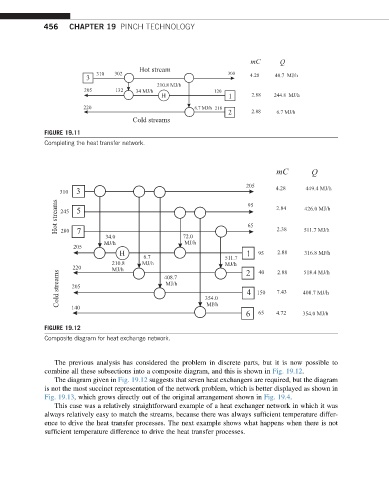
             FIGURE 19.12
             Composite diagram for heat exchange network.


                The previous analysis has considered the problem in discrete parts, but it is now possible to
             combine all these subsections into a composite diagram, and this is shown in Fig. 19.12.
                The diagram given in Fig. 19.12 suggests that seven heat exchangers are required, but the diagram
             is not the most succinct representation of the network problem, which is better displayed as shown in
             Fig. 19.13, which grows directly out of the original arrangement shown in Fig. 19.4.
                This case was a relatively straightforward example of a heat exchanger network in which it was
             always relatively easy to match the streams, because there was always sufficient temperature differ-
             ence to drive the heat transfer processes. The next example shows what happens when there is not
             sufficient temperature difference to drive the heat transfer processes.
   460   461   462   463   464   465   466   467   468   469   470