
Page 469 - Advanced thermodynamics for engineers
P. 469
460 CHAPTER 19 PINCH TECHNOLOGY
column of figures in Fig. 19.16, which has been achieved by adding 12.5 units of energy to the system.
It can be seen that in both cases the difference between Q h and Q c is 17.5 units of energy. If an energy
balance is applied to the streams defined in Table 19.3 then
X
dH i ¼ 3 ð130 70Þþ 1:5 ð120 55Þ 2 ð110 50Þ 4 ð115 80Þ
(19.3)
¼ 17:5
Hence, as stated previously, the energies obey the steady flow energy equation for the system
shown in Fig. 19.16.
There is now a point in the temperature range where the heat flow is zero: this point is called the
pinch. In this example it is at 80 C, which means that the pinch occurs at a cold stream temperature of
80 C and a hot stream temperature of 85 C. There are three important constraints regarding the
pinch:
1. Do not transfer heat across the pinch. Any heat flow across the pinch results in the same amount
of heat being added to every heat flow throughout the system, and hence increases Q h and Q c .
2. Do not use the cold sink above the pinch. If the system has been designed for minimised heat
flow, it does not reject any heat from itself. (see Fig. 19.16, where the heat rejection has been
made zero at the pinch.)
3. Do not use the hot source below the pinch. If the system has been designed for minimised heat
flow, it does not absorb any heat below the pinch.
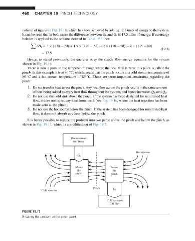
It is hence possible to reduce the problem into two parts: above the pinch and below the pinch, as
shown in Fig. 19.17, which is a modification of Fig. 19.7.
Hot reservoir
(utilities)
Hot streams
Q h
Above Below
the the
pinch pinch
Pinch Q c
Cold streams
Cold reservoir
(utilities)
FIGURE 19.17
Breaking the problem at the pinch point.