
Page 471 - Advanced thermodynamics for engineers
P. 471
462 CHAPTER 19 PINCH TECHNOLOGY
Hot streams mC Q
2 130 70 3.0 180
4 120 75 C 55 1.5 97.5
30 MJ/h
110 106.3 50
H 1 2.0 130
7.5 MJ/h 52.5 MJ/h 45 MJ/h 15 MJ/h
115 113.8 80
H 3 4.0 140
5 MJ/h 135MJ/h
Cold streams
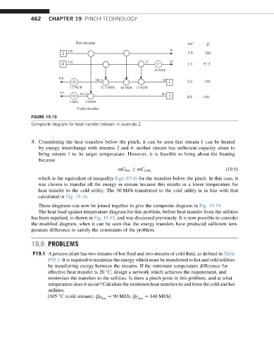
FIGURE 19.19
Composite diagram for heat transfer network in example 2.
4. Considering the heat transfers below the pinch, it can be seen that stream 1 can be heated
by energy interchange with streams 2 and 4: neither stream has sufficient capacity alone to
bring stream 1 to its target temperature. However, it is feasible to bring about the heating
because
mC hot mC cold (19.5)
which is the equivalent of inequality Eqn (19.4) for the transfers below the pinch. In this case, it
was chosen to transfer all the energy in stream because this results in a lower temperature for
heat transfer to the cold utility. The 30 MJ/h transferred to the cold utility is in line with that
calculated in Fig. 19.16.
These diagrams can now be joined together to give the composite diagram in Fig. 19.19.
The heat load against temperature diagram for this problem, before heat transfer from the utilities
has been supplied, is shown in Fig. 19.15, and was discussed previously. It is now possible to consider
the modified diagram, when it can be seen that the energy transfers have produced sufficient tem-
perature difference to satisfy the constraints of the problem.
19.6 PROBLEMS
P19.1 A process plant has two streams of hot fluid and two streams of cold fluid, as defined in Table
P19.1. It is required to minimise the energy which must be transferred to hot and cold utilities
by transferring energy between the streams. If the minimum temperature difference for
effective heat transfer is 20 C, design a network which achieves the requirement, and
minimises the transfers to the utilities. Is there a pinch point in this problem, and at what
temperature does it occur? Calculate the minimum heat transfers to and from the cold and hot
utilities.
¼ 140 MJ/h]
[105 C (cold stream); Q H min ¼ 90 MJ/h; Q C min