
Page 473 - Advanced thermodynamics for engineers
P. 473
464 CHAPTER 19 PINCH TECHNOLOGY
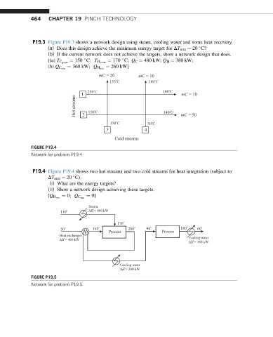
P19.3 Figure P19.3 shows a network design using steam, cooling water and some heat recovery.
(a) Does this design achieve the minimum energy target for DT min ¼ 20 C?
(b) If the current network does not achieve the targets, show a network design that does.
+
+ ¼ 170 C; Q C ¼ 480 kW; Q H ¼ 380 kW;
[(a) T C pinch ¼ 150 C; T H pinch
¼ 260 kW]
(b) Q C min ¼ 360 kW; Q H min
mC = 20 mC = 10
o
o
155 C 180 C
o
o
250 C 100 C
1 mC = 10
Hot streams 150 C 140 C
o
o
2
o
o
130 C 30 C mC = 50
3 4
Cold streams
FIGURE P19.4
Network for problem P19.4.
P19.4 Figure P19.4 shows two hot streams and two cold streams for heat integration (subject to
DT min ¼ 20 C).
(i) What are the energy targets?
(ii) Show a network design achieving these targets.
¼ 0]
[Q H min ¼ 0; Q C min
Steam,
o ΔH = 480 kW
110
o
170
50 o 165 o 200 o 90 o 180 o 60 o
Process Process
Heat exchanger
ΔH = 460 kW Cooling water
ΔH = 360 kW
Cooling water
ΔH = 200 kW
FIGURE P19.5
Network for problem P19.5.