
Page 168 - Advances in Biomechanics and Tissue Regeneration
P. 168
164 8. TOWARDS THE REAL-TIME MODELING OF THE HEART
Z
X
Y
FIG. 8.23 Superimposed template mesh (gray) and registered data mesh (green).
8.5.2 Numerical Examples
This section discusses the suitability of the two proposed standardization methods for patient-specific heart model-
ing. Here, the focus is on the diastolic filling phase where the heart responds passively to the increasing cavity filling
pressure. The PODI databases are populated from full-scale simulation results of 58 incremental time steps using the
EFG [81], implemented in SESKA [90] and on a desktop computer equipped with an Intel i7 processor (four physical
cores clocked at 3.4 GHz) and 8 GB of memory. Given that all datasets have been simulated using the same time steps,
the time standardization process was not required.
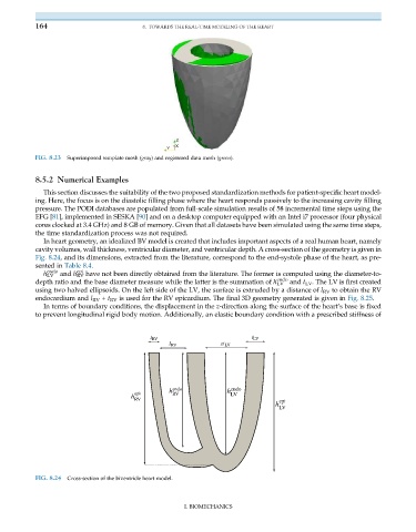
In heart geometry, an idealized BV model is created that includes important aspects of a real human heart, namely
cavity volumes, wall thickness, ventricular diameter, and ventricular depth. A cross-section of the geometry is given in
Fig. 8.24, and its dimensions, extracted from the literature, correspond to the end-systole phase of the heart, as pre-
sented in Table 8.4.
endo
epi
h LV and h RV have not been directly obtained from the literature. The former is computed using the diameter-to-
endo
depth ratio and the base diameter measure while the latter is the summation of h LV and t LV . The LV is first created
using two halved ellipsoids. On the left side of the LV, the surface is extruded by a distance of l RV to obtain the RV
endocardium and l RV + t RV is used for the RV epicardium. The final 3D geometry generated is given in Fig. 8.25.
In terms of boundary conditions, the displacement in the z-direction along the surface of the heart’s base is fixed
to prevent longitudinal rigid body motion. Additionally, an elastic boundary condition with a prescribed stiffness of
t t
FIG. 8.24 Cross-section of the biventricle heart model.
I. BIOMECHANICS