
Page 171 - Advances in Biomechanics and Tissue Regeneration
P. 171
8.5 PATIENT-SPECIFIC CARDIAC PODI COMPUTATION 167
FIG. 8.27 Perturbed heart geometry BV-1.
FIG. 8.28 Heart geometry of the problem at hand (BV-R), A ¼ 0.13 kPa.
EFG
Rama et al. [34]. The PODI results, U PODI , were then compared to the full-scale simulation of BV-R, U BV-R , and the L 2
norm error, based on Eq. (8.33), was computed as follows:
k U PODI U EFG k
i
i,BV R
ε BV R : (8.46)
‘ 2 norm ¼ EFG
k U
i,BV R k
8.5.2.1 Cube Template Standardization
8.5.2.1.1 COARSE TEMPLATE DISCRETIZATION
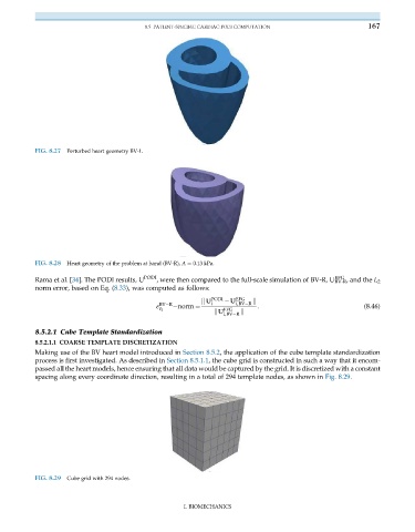
Making use of the BV heart model introduced in Section 8.5.2, the application of the cube template standardization
process is first investigated. As described in Section 8.5.1.1, the cube grid is constructed in such a way that it encom-
passed all the heart models, hence ensuring that all data would be captured by the grid. It is discretized with a constant
spacing along every coordinate direction, resulting in a total of 294 template nodes, as shown in Fig. 8.29.
FIG. 8.29 Cube grid with 294 nodes.
I. BIOMECHANICS