
Page 189 - Advances in Biomechanics and Tissue Regeneration
P. 189
9.3 EQUILIBRIUM APPLICATIONS: BOUNDARY CONDITIONS AND LOADING 185
muscles, cross-talk considerations, complexity in force-EMG relation, signal processing and normalization, and intro-
duction of gain factors [103, 112].
Using a hybrid MS model of the lower extremity with our detailed validated FE model of the knee joint, we resolve
the redundancy and estimate muscle forces using a kinematics-driven optimization approach [15, 20, 22, 35, 36]. In this
way, not only the passive properties of the knee joint are accurately represented, but also both joint moments (from
inverse dynamics and gait data) and joint kinematics (from gait data) are used to drive the model resulting in a syn-
ergistic passive-active simulation. By considering the measured kinematics, this kinematics-driven MS model can also
fall into the category of a biological approach as joint kinematics and human posture are controlled in static and tran-
sient movements by the central nervous system.
9.3 EQUILIBRIUM APPLICATIONS: BOUNDARY CONDITIONS AND LOADING
In knee joint biomechanics, under both active and passive conditions, proper consideration of joint loading and
boundary conditions are of prime importance as they both substantially affect results and subsequent comparisons
and validations. Here as follows are some sample applications of our FE model dealing with boundary conditions
and loading.
Careful selection of stable and fully unconstrained boundary conditions in experimental and model studies of any
complex articulation such as the knee joint is crucial. On the one hand, the constraints should be sufficient to avoid
instability (hypermobility), while on the other hand, they should not be excessive to artificially and inadvertently over-
constraint and stiffen the physiological response. In addition, if the intention is to represent and compare with an exist-
ing study, being in vivo, in vitro, or in silico, the model should replicate as closely as possible the corresponding bound-
ary conditions. For example, to investigate the passive TF response in full extension under 1000 N, Bendjaballah et al.
[11] applied the force on the primary (reference) node of the femur with the tibia completely fixed. For a stable and
unconstrained response, the femoral flexion-extension (F-E) and adduction-abduction (add-abd) rotations were also
fixed while leaving internal-external (I-E) rotations and all three translations at the femur free. Additional constraint on
I-E rotations was subsequently found to have a significant effect on knee biomechanics especially in the meniscecto-
mized case; the knee became stiffer in the axial direction, the ratio of medial/lateral contact load increased, and the
coupled displacements decreased as coupled I-E rotations were fixed [11]. In a similar study, but with the refined and
improved version of the model under up to 2000 N compression at full extension, Shirazi and Shirazi-Adl [87] used
equivalent, but reversed, boundary conditions with the femur fixed and tibia left free except in add-abd and F-E rota-
tions. They also found a much stiffer response as tibial coupled I-E rotations were also constrained. Foregoing bound-
ary conditions in the knee joint under axial compression force assure unconstrained motions with no interference with
the natural biomechanical roles of menisci, ligaments, and articular surfaces. Besides and equally important, artifact
loads are eliminated, and the response is no more dependent on the location where the large axial compression force is
applied on the femur or on the tibia.
Due to the joint instability and artifact moments caused by large compression forces, in vitro biomechanical inves-
tigations of the knee joint face the dilemma of how (joint constraints) and where (anterior-posterior, A-P and medial-
lateral, M-L, locations) to apply compression forces of physiological magnitudes [71, 113]. To circumvent these diffi-
culties under compression forces, in vitro studies impose additional constraints on rotations in sagittal and frontal
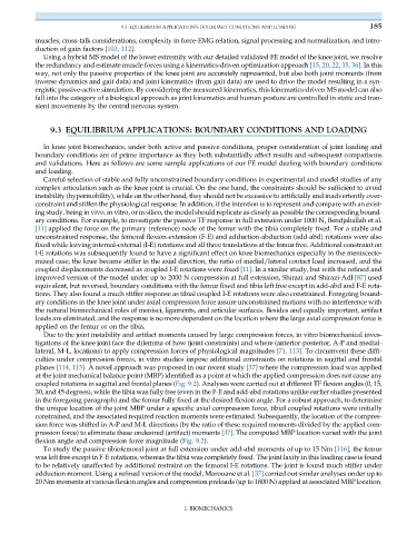
planes [114, 115]. A novel approach was proposed in our recent study [37] where the compression load was applied
at the joint mechanical balance point (MBP) identified as a point at which the applied compression does not cause any
coupled rotations in sagittal and frontal planes (Fig. 9.2). Analyses were carried out at different TF flexion angles (0, 15,
30, and 45 degrees), while the tibia was fully free (even in the F-E and add-abd rotations unlike earlier studies presented
in the foregoing paragraph) and the femur fully fixed at the desired flexion angle. For a robust approach, to determine
the unique location of the joint MBP under a specific axial compression force, tibial coupled rotations were initially
constrained, and the associated required reaction moments were estimated. Subsequently, the location of the compres-
sion force was shifted in A-P and M-L directions (by the ratio of these required moments divided by the applied com-
pression force) to eliminate these undesired (artifact) moments [37]. The computed MBP location varied with the joint
flexion angle and compression force magnitude (Fig. 9.2).
To study the passive tibiofemoral joint at full extension under add-abd moments of up to 15 Nm [116], the femur
was left free except in F-E rotations, whereas the tibia was completely fixed. The joint laxity in this loading case is found
to be relatively unaffected by additional restraint on the femoral I-E rotations. The joint is found much stiffer under
adduction moment. Using a refined version of the model, Marouane et al. [37] carried out similar analyses under up to
20 Nm moments at various flexion angles and compression preloads (up to 1800 N) applied at associated MBP location.
I. BIOMECHANICS