
Page 70 - Advances in Biomechanics and Tissue Regeneration
P. 70
4.2 MICROSTRUCTURAL MODELING OF THE CAROTID ARTERY 65
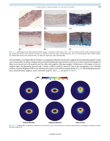
(A) (B) (C)
(D) (E) (F)
FIG. 4.1 Histological and immunohistochemical images of porcine carotid tissue (10 ). (A) Van Giesson elastin stain, proximal location.
(B) Antismooth muscle actin, proximal location. (C) Masson’s trichrome stain, proximal location. (D) Van Giesson elastin stain, distal location.
(E) Antismooth muscle actin, distal location. (F) Masson’s trichrome stain, distal location.
Theorientationofacollagenfiberin3DspacewasuniquelydefinedbyitselevationangleΦ anditsazimuthalangleΘ,which
were measured by (in-plane) rotating and (out-of-plane) tilting the stage. In Sáez et al.[27], two almost-symmetric families of
fibers were found (one with positive and the other with negative elevation angles). Furthermore, with respect to the azi-
muthal angle, the dispersion showed only a family of fibers could be observed. Due to the assumption of two families
of fibers, separate Bingham ODFs were introduced to capture each of them independently (Fig. 4.2). The fit Bingham param-
eters, mean elevation angle ϕ r , mean azimuthal angle θ r ,and κ 1, 2, 3 are given in Table 4.1.
FIG. 4.2 Collagen fiber orientation distribution for all proximal (up) and distal (down) samples represented by the Bingham orientation density
function (ODF) [27].
I. BIOMECHANICS