
Page 244 - Advances in Renewable Energies and Power Technologies
P. 244
4. Power Converter Technology and Control for PV Systems 217
Boost
PV Strings (optional) C dc Inverter Filter P o
DC DC
P PV Q Grid
C
Z g
DC AC
Load
i PV v PV PWM b v dc PWM inv
v g PCC
MPPT *
v dc Inverter i g
Mission Profiles Control
P * Q *
Communication Supervisory
Monitoring and Control command
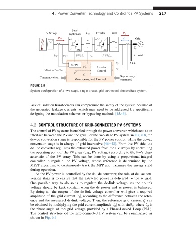
FIGURE 6.8
System configuration of a two-stage, single-phase, grid-connected photovoltaic system.
lack of isolation transformers can compromise the safety of the system because of
the generated leakage currents, which may need to be addressed by specifically
designing the modulation schemes or bypassing methods [45,46].
4.2 CONTROL STRUCTURE OF GRID-CONNECTED PV SYSTEMS
The control of PV systems is enabled through the power converter, which acts as an
interface between the PVand the grid. For the two-stage PV system in Fig. 6.8,the
dcedc conversion stage is responsible for the PV power control, while the dceac
conversion stage is in charge of grid interactive [46e48].Fromthe PV side,the
dcedc converter regulates the extracted power from the PV arrays by controlling
the operating point of the PV array (e.g., PV voltage) according to the PeVchar-
acteristic of the PV array. This can be done by using a proportional-integral
controller to regulate the PV voltage, whose reference is determined by the
MPPT algorithm, to continuously track the MPP and maximize the energy yield
during operation.
As the PV power is controlled by the dcedc converter, the role of dceac con-
version stage is to ensure that the extracted power is delivered to the ac grid.
One possible way to do so is to regulate the dc-link voltage, as the dc-link
voltage should be kept constant when the dc power and ac power is balanced.
By doing so, the output of the dc-link voltage controller will give a required
amplitude of the grid current ji g j, according to the difference between the refer-
ence and the measured dc-link voltage. Then, the reference grid current i can
g
be obtained by multiplying the grid current amplitude ji g j with sinq g ,where q g is
the phase angle of the grid voltage provided by a Phase-Locked Loop (PLL).
The control structure of the grid-connected PV system can be summarized as
shown in Fig. 6.9.