
Page 245 - Advances in Renewable Energies and Power Technologies
P. 245
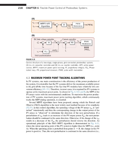
218    CHAPTER 6 Flexible Power Control of Photovoltaic Systems


                              (A)


                              (B)


                         FIGURE 6.9
                         Control structure of a two-stage, single-phase, grid-connected photovoltaic system:
                         (A) dcedc converter controller and (B) dceac inverter controller. APC, active power
                         control; MPPT, maximum power point tracking; PI, proportional integral; PLL, Phase-
                         locked loop; PR, proportional resonant; PWM, pulse width modulation.


                         4.3 MAXIMUM POWER POINT TRACKING ALGORITHMS
                         In PV systems, one main consideration is the efficiency of the power production of
                         the system. It is desirable that the PV systems deliver the maximum available power
                         to the grid all the time because of the fact that PV modules have relatively low con-
                         version efficiency [49e51]. Therefore, in most cases, it is required for PV systems to
                         operate at the maximum power point. As shown in Fig. 6.10A and B, the MPP of the
                         PVarrays varies with the environmental conditions. To maximize the power produc-
                         tion of PV systems, maximum power point tracking algorithm, which continuously
                         tracks the MPP during operation, is essential.
                            Several MPPT algorithms have been proposed, among which the Perturb and
                         Observe (P&O) algorithm is the most widely used method because of its simplicity
                         [52,53]. In this control algorithm, the operating voltage of the PV arrays v pv is “per-
                         turbed” intentionally and then the corresponding change in the output power of the
                         PV arrays is “observed” to determine the direction of the next perturbation. If a
                         perturbation of v pv leads to an increase of the PVoutput power P pv , the next pertur-
                         bation should be continued in the same direction. Otherwise, if the change of the v pv
                         results in a decrease of the P pv , the perturbation should reverse the direction. An
                         operational principle of the P&O MPPT algorithm is demonstrated in Fig. 6.11,
                         where the initial operating point of the PV system is higher than the MPP (i.e., point
                         A). When the operating point is perturbed from point A / B, the change in the PV
                         power is positive. Thus, the next perturbation is continued in the same direction (i.e.,