
Page 246 - Advances in Renewable Energies and Power Technologies
P. 246
4. Power Converter Technology and Control for PV Systems 219
(A) (B)
5 80 5 80
MPP MPP
1000 W/m 2
4 800 W/m 2 60 4 3 (A) 60
Current (A) 3 2 600 W/m 2 40 Power (W) Current 2 40 Power (W)
1 20 1 50 ºC 25 ºC 0 ºC 20
0 0 0 0
0 5 10 15 20 25 0 5 10 15 20 25
Voltage (V) Voltage (V)
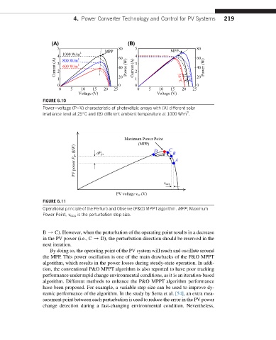
FIGURE 6.10
Powerevoltage (PeV) characteristic of photovoltaic arrays with (A) different solar
2
irradiance level at 25 C and (B) different ambient temperature at 1000 W/m .
Maximum Power Point
(MPP)
(kW) dP pv D C B
PV power P pv A
v step
PV voltage v pv (V)
FIGURE 6.11
Operational principle of the Perturb and Observe (P&O) MPPTalgorithm. MPP, Maximum
Power Point, v step is the perturbation step size.
B / C). However, when the perturbation of the operating point results in a decrease
in the PV power (i.e., C / D), the perturbation direction should be reserved in the
next iteration.
By doing so, the operating point of the PV system will reach and oscillate around
the MPP. This power oscillation is one of the main drawbacks of the P&O MPPT
algorithm, which results in the power losses during steady-state operation. In addi-
tion, the conventional P&O MPPT algorithm is also reported to have poor tracking
performance under rapid change environmental conditions, as it is an iteration-based
algorithm. Different methods to enhance the P&O MPPT algorithm performance
have been proposed. For example, a variable step size can be used to improve dy-
namic performance of the algorithm. In the study by Serra et al. [54], an extra mea-
surement point between each perturbation is used to reduce the error in the PV power
change detection during a fast-changing environmental condition. Nevertheless,