
Page 250 - Advances in Renewable Energies and Power Technologies
P. 250
5. Flexible Active Power Control of PV Systems 223
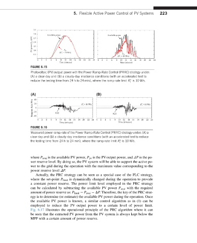
FIGURE 6.15
Photovoltaic (PV) output power with the Power Ramp-Rate Control (PRRC) strategy under:
(A) a clear-day and (B) a cloudy-day irradiance conditions (with an accelerated test to
reduce the testing time from 24 h to 24 min), where the ramp-rate limit R is 10 W/s.
r
(A) 40 (B)
Ramp rate R r(t)(W/s) -20 0 R r(t) R r =10 W/s R r(t) R r =10 W/s
20
*
*
-40
0 2 4 6 8 10 12 14 16 18 20 22 24 0 2 4 6 8 10 12 14 16 18 20 22 24
Time (minutes) Time (minutes)
FIGURE 6.16
Measured power ramp-rate of the Power Ramp-Rate Control (PRRC) strategy under: (A) a
clear-day and (B) a cloudy-day irradiance conditions (with an accelerated test to reduce
the testing time from 24 h to 24 min), where the ramp-rate limit R is 10 W/s.
r
where P avai is the available PV power, P pv is the PVoutput power, and DP is the po-
wer reserve level. By doing so, the PV system will be able to support the active po-
wer to the grid during the operation with the maximum value corresponding to the
power reserve level DP.
Actually, the PRC strategy can be seen as a special case of the PLC strategy,
where the set-point P limit is dynamically changed during the operation to provide
a constant power reserve. The power limit level employed in the PRC strategy
can be calculated by subtracting the available PV power P avai with the required
amount of power reserve as: P limit ¼ P avai DP. Therefore, the key of the PRC strat-
egy is to determine (or estimate) the available PV power during the operation. Once
the available PV power is known, a similar control algorithm as in (1) can be
employed to reduce the PV output power to a certain level of power limit.
Fig. 6.17 illustrates the operational principle of the PRC algorithm where it can
be seen that the extracted PV power from the PV system is always kept below the
MPP with a certain amount of power reserve.