
Page 52 - Advances in Renewable Energies and Power Technologies
P. 52
4. The Solar Cells 25
FIGURE 1.19
Choice of semiconductor material according to the cutoff wavelength.
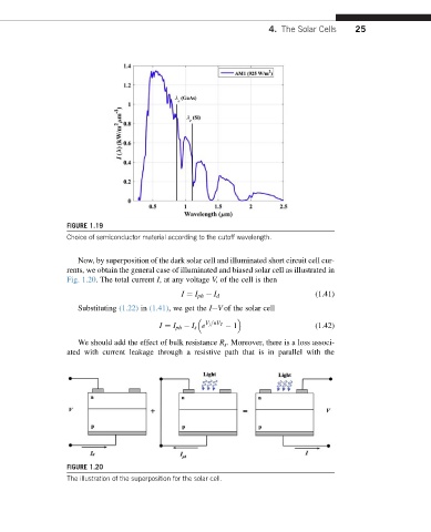
Now, by superposition of the dark solar cell and illuminated short circuit cell cur-
rents, we obtain the general case of illuminated and biased solar cell as illustrated in
Fig. 1.20. The total current I, at any voltage V, of the cell is then
I ¼ I ph I d (1.41)
Substituting (1.22) in (1.41), we get the IeV of the solar cell
I ¼ I ph I s e V j =nV T 1 (1.42)
We should add the effect of bulk resistance R s . Moreover, there is a loss associ-
ated with current leakage through a resistive path that is in parallel with the
FIGURE 1.20
The illustration of the superposition for the solar cell.