
Page 81 - Advances in Renewable Energies and Power Technologies
P. 81
54 CHAPTER 1 Solar Cells and Arrays: Principles, Analysis, and Design
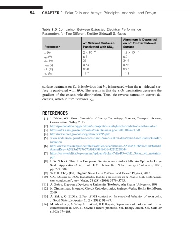
Table 1.5 Comparison Between Extracted Electrical Performance
Parameters for Two Different Emitter Sidewall Surfaces
Aluminum Is Deposited
D D
n Sidewall Surface Is on n Emitter Sidewall
Parameter Passivated with SiO 2 Surface
I s (A) 2 10 18 1.9 10 17
I sc (V) 6.3 6.2
J sc (A) 35 34.4
V oc (V) 0.54 0.52
FF (%) 80.8 80.7
h c (%) 11.7 11.1
þ
surface treatment on V oc . It is obvious that V oc is increased when the n sidewall sur-
face is passivated with SiO 2 . The reason is that the SiO 2 passivation decreases the
gradient of the excess hole distribution. Thus, the reverse saturation current de-
creases, which in turn increases V oc .
REFERENCES
[1] J. Fricke, W.L. Borst, Essentials of Energy Technology: Sources, Transport, Storage,
Conservation, Wiley, 2013.
[2] http://pveducation.org/pvcdrom/2-properties-sunlight/solar-radiation-earths-surface.
[3] https://ntrs.nasa.gov/archive/nasa/casi.ntrs.nasa.gov/19810016493.pdf.
[4] http://www.nrel.gov/docs/legosti/old/3895.pdf.
[5] www.ncdc.noaa.gov/data-access/land-based-station-data/land-based-datasets/solar-
radiation.
[6] https://www.researchgate.net/file.PostFileLoader.html?id¼553e4871d685ccd10e8b4618
&assetKey¼AS%3A273765705945088%401442282238044.
[7] https://ocw.tudelft.nl/wp-content/uploads/Solar-Cells-R3eCH3_Solar_cell_materials.
pdf.
[8] H.W. Schock, Thin Film Compound Semiconductor Solar Cells: An Option for Large
Scale Applications?, in: Tenth E.C. Photovoltaic Solar Energy Conference, 1991,
pp. 777e782.
[9] W.C.H. Choy (Ed.), Organic Solar Cells Materials and Device Physics, 2013.
[10] C.C. Stoumpos, M.G. Kanatzidis, Halide perovskites: poor Man’s high-performance
semiconductors”, Adv. Mater. 28 (28) (2016) 5778e5793.
[11] A. Zekry, Electronic Devices: A University Textbook, Ain Shams University, 1998.
[12] H. Zimmerman, Integrated Circuit Optoelectronics, Springer-Verlag Berlin Heidelberg,
2010.
[13] A. Zekry, G. ElDllal, Effect of MS contact on the electrical behavior of solar cells,
J. Solid State Electronics 31 (1) (1988) 91e97.
[14] M. Abdelnaby, A. Zekry, F. Elakkad, H.F. Ragaie, Dependence of dark current on zinc
concentration in ZnxCd1-xS/ZnTe hetero-junctions, Sol. Energy Mater. Sol. Cells 29
(1993) 97e108.