
Page 53 - Aerodynamics for Engineering Students
P. 53
36 Aerodynamics for Engineering Students
(a)
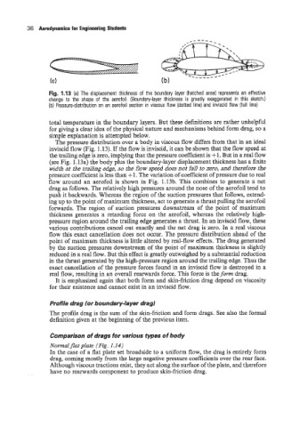
Fig. 1.13 (a) The displacement thickness of the boundary layer (hatched area) represents an effective
change to the shape of the aerofoil. (Boundary-layer thickness is greatly exaggerated in this sketch.)
(b) Pressure-distribution on an aerofoil section in viscous flow (dotted line) and inviscid flow (full line)
total temperature in the boundary layers. But these definitions are rather unhelpful
for giving a clear idea of the physical nature and mechanisms behind form drag, so a
simple explanation is attempted below.
The pressure distribution over a body in viscous flow differs from that in an ideal
inviscid flow (Fig. 1.13). If the flow is inviscid, it can be shown that the flow speed at
the trailing edge is zero, implying that the pressure coefficient is +l. But in a real flow
(see Fig. 1.13a) the body plus the boundary-layer displacement thickness has a finite
width at the trailing edge, so the flow speed does not fall to zero, and therefore the
pressure coefficient is less than +l. The variation of coefficient of pressure due to real
flow around an aerofoil is shown in Fig. 1.13b. This combines to generate a net
drag as follows. The relatively high pressures around the nose of the aerofoil tend to
push it backwards. Whereas the region of the suction pressures that follows, extend-
ing up to the point of maximum thickness, act to generate a thrust pulling the aerofoil
forwards. The region of suction pressures downstream of the point of maximum
thickness generates a retarding force on the aerofoil, whereas the relatively high-
pressure region around the trailing edge generates a thrust. In an inviscid flow, these
various contributions cancel out exactly and the net drag is zero. In a real viscous
flow this exact cancellation does not occur. The pressure distribution ahead of the
point of maximum thickness is little altered by real-flow effects. The drag generated
by the suction pressures downstream of the point of maximum thickness is slightly
reduced in a real flow. But this effect is greatly outweighed by a substantial reduction
in the thrust generated by the high-pressure region around the trailing edge. Thus the
exact cancellation of the pressure forces found in an inviscid flow is destroyed in a
real flow, resulting in an overall rearwards force. This force is the form drag.
It is emphasized again that both form and skin-friction drag depend on viscosity
for their existence and cannot exist in an inviscid flow.
Profile drag for boundary-layer drag)
The profile drag is the sum of the skin-friction and form drags. See also the formal
definition given at the beginning of the previous item.
Comparison of drags for various types of body
Normalflat plate (Fig. 1.14)
In the case of a flat plate set broadside to a uniform flow, the drag is entirely form
drag, coming mostly from the large negative pressure coefficients over the rear face.
Although viscous tractions exist, they act along the surface of the plate, and therefore
have no rearwards component to produce skin-friction drag.