
Page 55 - Aerodynamics for Engineering Students
P. 55
38 Aerodynamics for Engineering Students
- -- A proximate edge
of wake
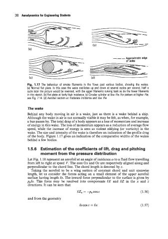
Fig. 1.17 The behaviour of smoke filaments in the flows past various bodies, showing the wakes.
(a) Normal flat plate. In this case the wake oscillates up and down at several cycles per second. Half a
cycle later the picture would be reversed, with the upper filaments curving back as do the lower filaments
in this sketch. (b) Flat plate at fairly high incidence. (c) Circular cylinder at low Re. For pattern at higher Re,
see Fig. 7.14. (d) Aerofoil section at moderate incidence and low Re
The wake
Behind any body moving in air is a wake, just as there is a wake behind a ship.
Although the wake in air is not normally visible it may be felt, as when, for example,
a bus passes by. The total drag of a body appears as a loss of momentum and increase
of energy in this wake. The loss of momentum appears as a reduction of average flow
speed, while the increase of energy is seen as violent eddying (or vorticity) in the
wake. The size and intensity of the wake is therefore an indication of the profile drag
of the body. Figure 1.17 gives an indication of the comparative widths of the wakes
behind a few bodies.
1.5.6 Estimation of the coefficients of lift, drag and pitching
moment from the pressure distribution
Let Fig. 1.18 represent an aerofoil at an angle of incidence .a to a fluid flow travelling
from left to right at speed V. The axes Ox and Oz are respectively aligned along and
perpendicular to the chord line. The chord length is denoted by c.
Taking the aerofoil to be a wing section of constant chord and unit spanwise
length, let us consider the forces acting on a small element of the upper aerofoil
surface having length 6s. The inward force perpendicular to the surface is given by
puSs. This force may be resolved into components SX and 62 in the x and z
directions. It can be seen that
62, = -pu cos E (1.56)
and from the geometry
6s cos E = sx (1.57)