
Page 430 - Air Pollution Control Engineering
P. 430
10_chap_wang.qxd 05/05/2004 5:10 pm Page 402
402 Lawrence K.Wang et al.
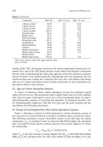
Table 2 (Continued)
a
a
Compound Mol. Wt. LEL (% vol) UEL (% vol)
n-Propyl alcohol 60.09 2.2 14.0
n-Butyl alcohol 74.12 1.7 12.0
n-Amyl alcohol 88.15 1.2 10.0
n-Hexyl alcohol 102.17 1.2 7.9
Dimethyl ether 46.07 3.4 27.0
Diethyl ether 74.12 1.9 36.0
Ethyl propl ether 88.15 1.7 9.0
Diisopropyl ether 102.17 1.4 7.9
Acetaldehyde 44.05 4.0 36.0
Propionaldehyde 58.08 2.9 14.0
Acetone 58.08 2.6 13.0
Methyl ethyl ketone 72.10 1.9 10.0
Methyl propyl ketone 86.13 1.6 8.2
Diethyl ketone 86.13 1.6
Methyl butyl ketone 100.16 1.4 8.0
a LEL: lower explosive limit; UEL: upper explosive limit.
Source: US EPA.
loading of the VOC, the designer determines the carbon requirement, whereas the vol-
umetric flow rate of the VOC-laden emission stream allows the designer to determine
the size of the vessels housing the carbon, the capacities of the fans and motors required,
and the diameter of the internal ductwork. Although the other two parameters are less
significant than mass loading and volumetric flow rate, they will influence the design
and cost of a carbon adsorption system. Further discussions on these parameters are
presented in detail in later sections.
4.2. Type of Carbon Adsorption Systems
A variety of industries utilize carbon adsorption systems for pollution control
and/or solvent recovery. The operational mode is usually batch and can involve multiple
beds. The five types of adsorption system are (1) fixed regenerative beds, (2) dispos-
able/rechargeable canisters, (3) traveling bed adsorbers, (4) fluidized adsorbers, and
(5) chromatographic baghouses. The first two types are the most common and are
described in the following subsections.
4.3 Design of Fixed Regenerative Bed Carbon Adsorption Systems
Figure 1 illustrates a typical two-bed regenerative carbon adsorption system. A
two-step process can be performed to design a fixed-bed carbon adsorption system.
The following procedures assume a horizontal system. In the first step, the carbon
requirement, C , is estimated based on expected inlet HAP loading, the adsorption
req
time, the number of beds, and the working capacity of the carbon. Equation (3) shows
this relationship:
C = (M θ [1 + (ND/NA)])/W (3)
req HAP ad c
where C is the total amount of carbon required (lb), M is the HAP inlet loading
req HAP
(lb/h), θ is the adsorption time (h), ND is the number of beds desorbing, NA is the
ad