
Page 433 - Air Pollution Control Engineering
P. 433
10_chap_wang.qxd 05/05/2004 5:10 pm Page 405
Gas Phase Activated Carbon Adsorption 405
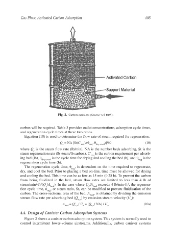
Fig. 2. Carbon canisters (Source: US EPA).
carbon will be required. Table 3 provides outlet concentrations, adsorption cycle times,
and regeneration cycle times at these two ratios.
Equation (10) is used to determine the flow rate of steam required for regeneration:
Q = NA [St(C' )/(θ –θ )]/60 (10)
s req req dry-cool
where Q is the steam flow rate (lb/min), NA is the number beds adsorbing, St is the
s
steam regeneration rate (lb steam/lb carbon), C' req is the carbon requirement per adsorb-
ing bed (lb), θ is the cycle time for drying and cooling the bed (h), and θ is the
dry-cool reg
regeneration cycle time (h).
The regeneration cycle time, θ , is dependent on the time required to regenerate,
reg
dry, and cool the bed. Prior to placing a bed on-line, time must be allowed for drying
and cooling the bed. This time can be as few as 15 min (0.25 h). To prevent the carbon
from being fluidized in the bed, steam flow rates are limited to less than 4 lb of
2
2
steam/min/-ft (Q /A ). In the case where Q /A exceeds 4 lb/min-ft , the regenera-
s bed s bed
tion cycle time, θ , or steam ratio, St, can be modified to prevent fluidization of the
reg
carbon. The cross-sectional area of the bed, A , is obtained by dividing the emission
bed
stream flow rate per adsorbing bed (Q ) by emission stream velocity (U ):
e,a e
A = Q' / U = (Q / NA) / U (10a)
bed e,a e e,a e
4.4. Design of Canister Carbon Adsorption Systems
Figure 2 shows a canister carbon adsorption system. This system is normally used to
control intermittent lower-volume airstreams. Additionally, carbon canister systems