
Page 431 - Air Pollution Control Engineering
P. 431
10_chap_wang.qxd 05/05/2004 5:10 pm Page 403
Gas Phase Activated Carbon Adsorption 403
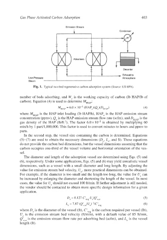
Fig. 1. Typical two-bed regenerative carbon adsorption system (Source: US EPA).
number of beds adsorbing, and W is the working capacity of carbon (lb HAP/lb of
c
carbon). Equation (4) is used to determine M :
HAP
M = 6.0 × 10 −5 (HAP )(Q )(D ) (4)
HAP e e HAP
where M is the HAP inlet loading (lb HAP/h), HAP is the HAP emission stream
HAP e
concentration (ppmv), Q is the HAP emission stream flow rate (scfm), and D is the
e HAP
3
gas density of the HAP (lb/ft ). The factor 6.0 × 10 −5 is obtained by multiplying 60
min/h by 1 part/1,000,000. This factor is used to convert minutes to hours and ppmv to
parts.
In the second step, the vessel size containing the carbon is determined. Equations
(5)–(7) are used to obtain the necessary dimensions (D ,L , and S). These equations
v v
do not provide the carbon bed dimensions, but the vessel dimensions assuming that the
carbon occupies one-third of the vessel volume and horizontal orientation of the ves-
sel.
The diameter and length of the adsorption vessel are determined using Eqs. (5) and
(6), respectively. Under some applications, Eqs. (5) and (6) may yield unrealistic vessel
dimensions, such as a vessel with a small diameter and long length. By adjusting the
value for emission stream bed velocity, U , more practical dimensions can be obtained.
e
For example, if the diameter is too small and the length too long, the value for U can
e
be increased by enlarging the diameter and shortening the length of the vessel. In most
cases, the value for U should not exceed 100 ft/min. If further adjustment is still needed,
e
the vendor should be contacted to obtain more specific design information for a given
application.
D = 0.127 C' U /Q' (5)
v req e e,a
2
L = 7.87 (Q' /U ) /C' (6)
v e,a e req
where D is the diameter of the vessel (ft), C' is the carbon required per vessel (lb),
v req
U is the emission stream bed velocity (ft/min), with a default value of 85 ft/min,
e
Q' is the emission stream flow rate per adsorbing bed (acfm), and L is the vessel
e,a v
length (ft).