
Page 467 - Air pollution and greenhouse gases from basic concepts to engineering applications for air emission control
P. 467
448 15 Air Monitoring
Static pressure port
(multiple), 2
To pressure sensor, P
1
1
Stagnation Pitot tube To pressure
point, 1 sensor, P 2
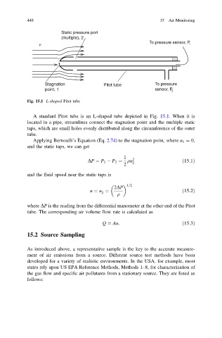
Fig. 15.1 L-shaped Pitot tube
A standard Pitot tube is an L-shaped tube depicted in Fig. 15.1. When it is
located in a pipe, streamlines connect the stagnation point and the multiple static
taps, which are small holes evenly distributed along the circumference of the outer
tube.
Applying Bernoulli’s Equation (Eq. 2.74) to the stagnation point, where u 1 ¼ 0,
and the static taps, we can get
1 2
DP ¼ P 1 P 2 ¼ qu 2 ð15:1Þ
2
and the fluid speed near the static taps is
1=2
2DP
u ¼ u ¼ ð15:2Þ
2 q
where DP is the reading from the differential manometer at the other end of the Pitot
tube. The corresponding air volume flow rate is calculated as
Q ¼ Au: ð15:3Þ
15.2 Source Sampling
As introduced above, a representative sample is the key to the accurate measure-
ment of air emissions from a source. Different source test methods have been
developed for a variety of realistic environments. In the USA, for example, most
states rely upon US EPA Reference Methods, Methods 1–8, for characterization of
the gas flow and specific air pollutants from a stationary source. They are listed as
follows: