
Page 29 - Air and Gas Drilling Manual
P. 29
1-6 Air and Gas Drilling Manual
with an on-board prime mover which operates the rotary table, drawworks, and mud
pump. The axial force on the drill bit is provided by drill collars. The torque and
rotation at the top of the drill string is provided by the kelly and the rotary table.
The double drilling rigs have a “crows nest” or “derrick board” nearly midway up the
mast. This allows these rigs to pull stands of two drill collar joints or two drill
pipe joints. These rigs can carry out drilling operations using drilling mud (with the
on-board mud pump) or using compressed air or gas drilling fluids (with external
compressors). A few of these drilling rigs are capable of drilling with their masts at
a 45˚ angle to the vertical. The prime mover for these rigs is usually diesel fueled,
but can easily be converted to propane or natural gas fuels.
Triple drilling rigs are available in a variety of configurations. Nearly all of
these drilling rigs are assembled and erected from premanufactured sections. The
vertical tower structure on these drilling rigs are called derricks. The smaller triple
land rigs can drill to approximately 20,000 ft and utilize Range 2 drill collars and
drill pipe. Very large triple drilling rigs are used on offshore platforms. These rigs
can utilize Range 3 drill collars and drill pipe.
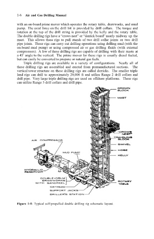
Figure 1-5: Typical self-propelled double drilling rig schematic layout.