
Page 30 - Air and Gas Drilling Manual
P. 30
Chapter 1: Introduction 1-7
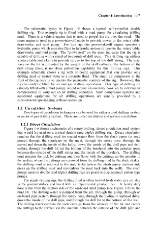
The schematic layout in Figure 1-5 shows a typical self-propelled double
drilling rig. This example rig is fitted with a mud pump for circulating drilling
mud. There is a vehicle engine that is used to propel the rig over the road. The
same engine is used in a power-take-off mode to provide power to the rotary table,
drawworks, and mud pump. For this rig, this power-take-off engine operates a
hydraulic pump which provides fluid to hydraulic motors to operate the rotary table,
drawworks, and mud pump. The “crows nest” on the mast indicates that the rig is
capable of drilling with a stand of two joints of drill pipe. This drilling rig utilizes
a rotary table and a kelly to provide torque to the top of the drill string. The axial
force on the bit is provided by the weight of the drill collars at the bottom of the
drill string (there is no chain pull-down capability for this drilling rig). This
example schematic shows a rig with on-board equipment that can provide only
drilling mud or treated water as a circulate fluid. The small air compressor at the
front of the rig deck is to operate the pneumatic controls of the rig. However, this
rig can easily be fitted for air and gas drilling operations. This type of drilling rig
(already fitted with a mud pump), would require an auxiliary hook up to external air
compressor(s) to carry out an air drilling operation. Such compressor systems and
associated equipment for air drilling operations are usually provided by a
subcontractor specializing in these operations.
1.2 Circulation Systems
Two types of circulation techniques can be used for either a mud drilling system
or an air or gas drilling system. These are direct circulation and reverse circulation.
1.2.1 Direct Circulation
Figure 1-6 shows a schematic of a rotary drilling, direct circulation mud system
that would be used on a typical double (and triple) drilling rig. Direct circulation
requires that the drilling mud (or treated water) flow from the slush pump (or mud
pump), through the standpipe on the mast, through the rotary hose, through the
swivel and down the inside of the kelly, down the inside of the drill pipe and drill
collars, through the drill bit (at the bottom of the borehole) into the annulus space
between the outside of the drill string and the inside of the borehole. The drilling
mud entrains the rock bit cuttings and then flows with the cuttings up the annulus to
the surface where the cuttings are removed from the drilling mud by the shale shaker;
the drilling mud is returned to the mud tanks (where the slush pump suction side
picks up the drilling mud and recirculates the mud back into the well). The slush
pumps used on double (and triple) drilling rigs are positive displacement piston type
pumps.
For single drilling rigs, the drilling fluid is often treated fresh water in a pit dug
in the ground surface and lined with an impermeable plastic liner. A heavy duty
hose is run from the suction side of the on-board mud pump (see Figure 1-5) to the
mud pit. The drilling water is pumped from the pit, through the pump, through an
on-board pipe system, through the rotary hose, through the hydraulic tophead drive,
down the inside of the drill pipe, and through the drill bit to the bottom of the well.
The drilling water entrains the rock cuttings from the advance of the bit and carries
the cuttings to the surface via the annulus between the outside of the drill pipe and